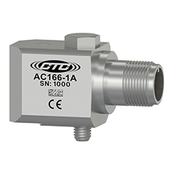
AC166 Series

Negative Voltage Accelerometer, Side Exit 3 Pin Connector, 100 mV/g, ±5%
AC166-1A
3 Pin Connector
Connector Pin Polarity
A (+) Signal
B (-) Power-Negative
C (+) Common/Power
A drawing showing the dimensions and pin configuration of a CTC AC166 industrial accelerometer.
Stock Product
AC166-2C
CB105 Integral Cable
Conductor Polarity
Red (+) Signal
Black (-) Common
White (+) Common/Power
Shield Cable Drain Wire
A drawing showing the dimensions and pin configuration of a CTC AC166 industrial accelerometer with integral cable.
Built To Order
AC166-3C
CB218 Armored Integral Cable
Conductor Polarity
Red (+) Signal
Black (-) Common
White (+) Common/Power
Shield Cable Drain Wire
A drawing showing the dimensions and pin configuration of a CTC AC166 industrial accelerometer with armored integral cable.
Built To Order
AC166
Wiring Diagram
Negative voltage wiring
Specifications Standard Metric
Part Number AC166 M/AC166
Sensitivity (±5%) 100 mV/g
Frequency Response (±3dB) 300-600,000 CPM 5-10000 Hz
Frequency Response (±10%) 600-180,000 CPM 10-3000 Hz
Dynamic Range ± 60 g, peak
*Vsource ≤-20V, 8.5Vbias
Electrical
Settling Time <2 Seconds
Voltage Source (IEPE) -20 to -28 VDC
Constant Current Excitation <1 mA
Broadband Noise Floor
(10 to 15k Hz)
.002 g RMS
Output Impedance <5 ohm
Bias Output Voltage -8.5 VDC Nominal
Case Isolation >108 ohm
Specifications Standard Metric
Environmental
Operating Temperature Range -58 to 250 °F -50 to 121 °C
Maximum Shock Protection 5,000 g, peak
Sealing Welded, Hermetic
SIL Rating SIL 2
Physical
Sensing Element PZT Ceramic
Sensing Structure Shear Mode
Weight 5.1 oz 145 grams
Case Material 316 Stainless Steel
Connector (Non-Integral) 3 Pin MIL-C-5015
Resonant Frequency 1,320,000 CPM 22000 Hz
Mounting Torque 2 to 5 ft. lbs. 2,7 to 6,8 Nm
Mounting Hardware Supplied 1/4-28 Captive Bolt M6x1 Captive Bolt
Calibration Certificate CA10

Typical Frequency Response

A line graph showing the frequency resopnse of a CTC AC166 condition monitoring sensor.