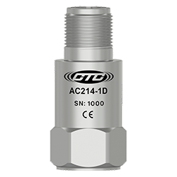
AC214 Series
Premium, Low Frequency Accelerometer, Top Exit 2 Pin Connector, 1,000 mV/g, ±5%

Product Features
Designed for Low-Speed Rotors, Wind Turbine Main Bearings, Gear Box Inputs, and May Also Be Used for High Frequency Detection
May be Used with Any Application That Requires Low and High Frequency Measurements
- 1000 mV/g Sensitivity
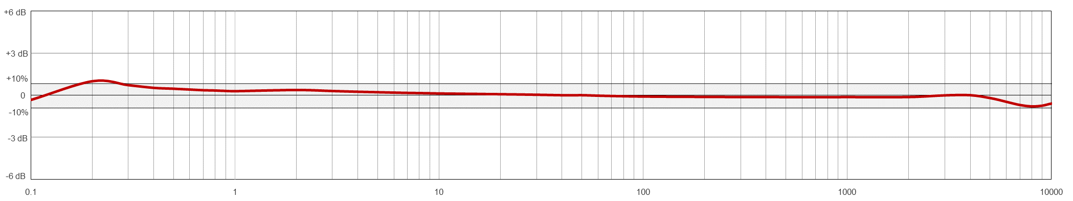
- 0.1 Hz to 10 kHz Frequency Response (± 3dB)
- Standard 2 Pin MIL Connection or Integral Cable
Note: Integral Cable Options are Only for Permanent Monitoring Applications .
-6N Integral Cable Option Features Food Safe FDA Compliant 21 CFR 177.1330 Polyolefin Heat Shrink
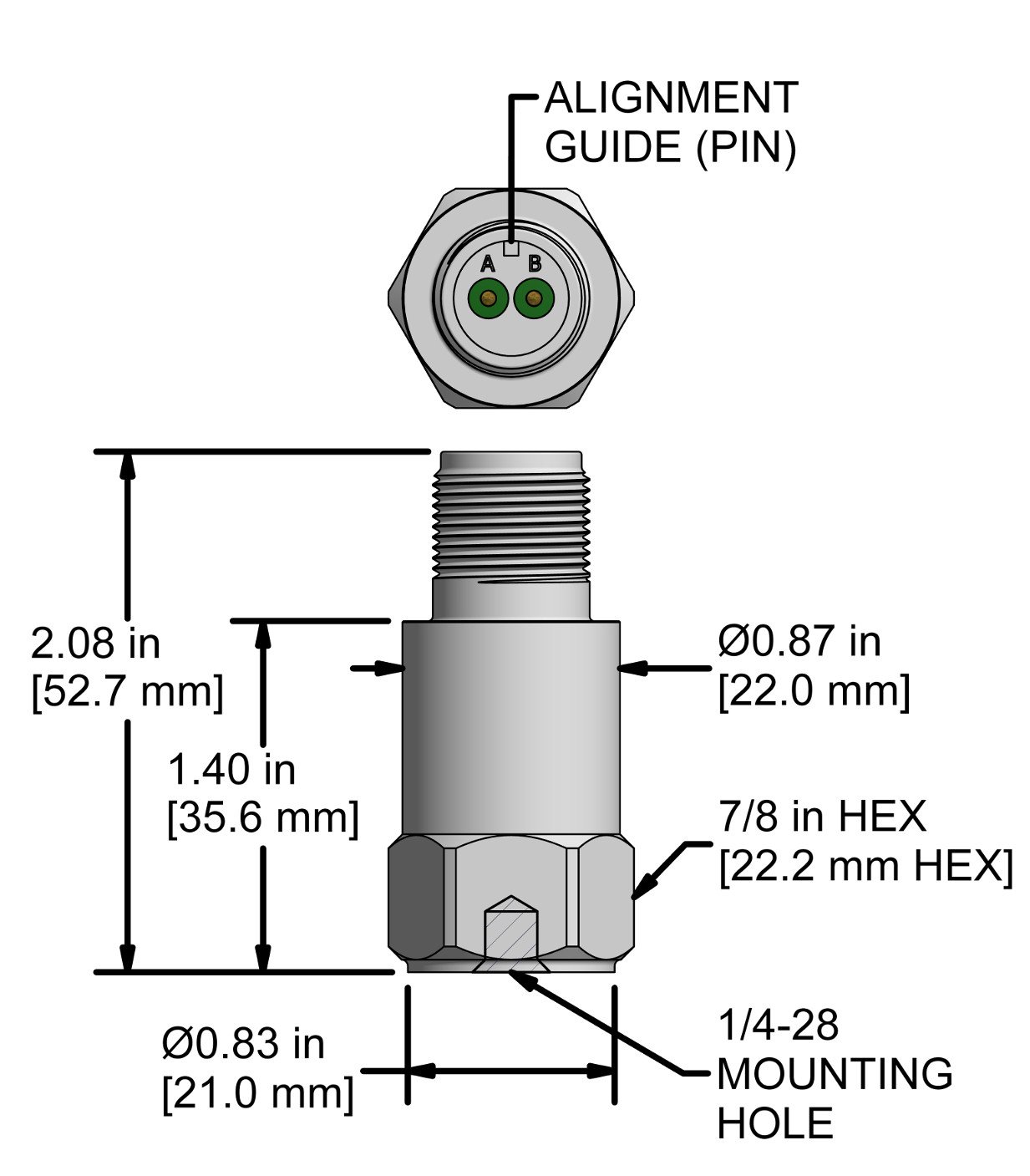
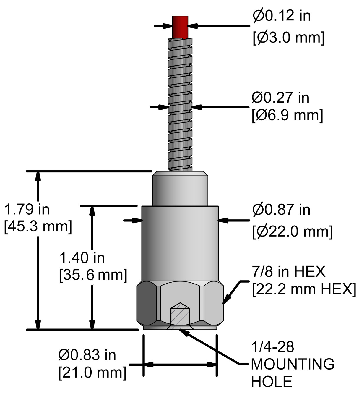
AC214-1D
2 Pin Connector
| Connector Pin | Polarity |
| A | (+) Signal/Power |
| B | (-) Common |
Stock Product
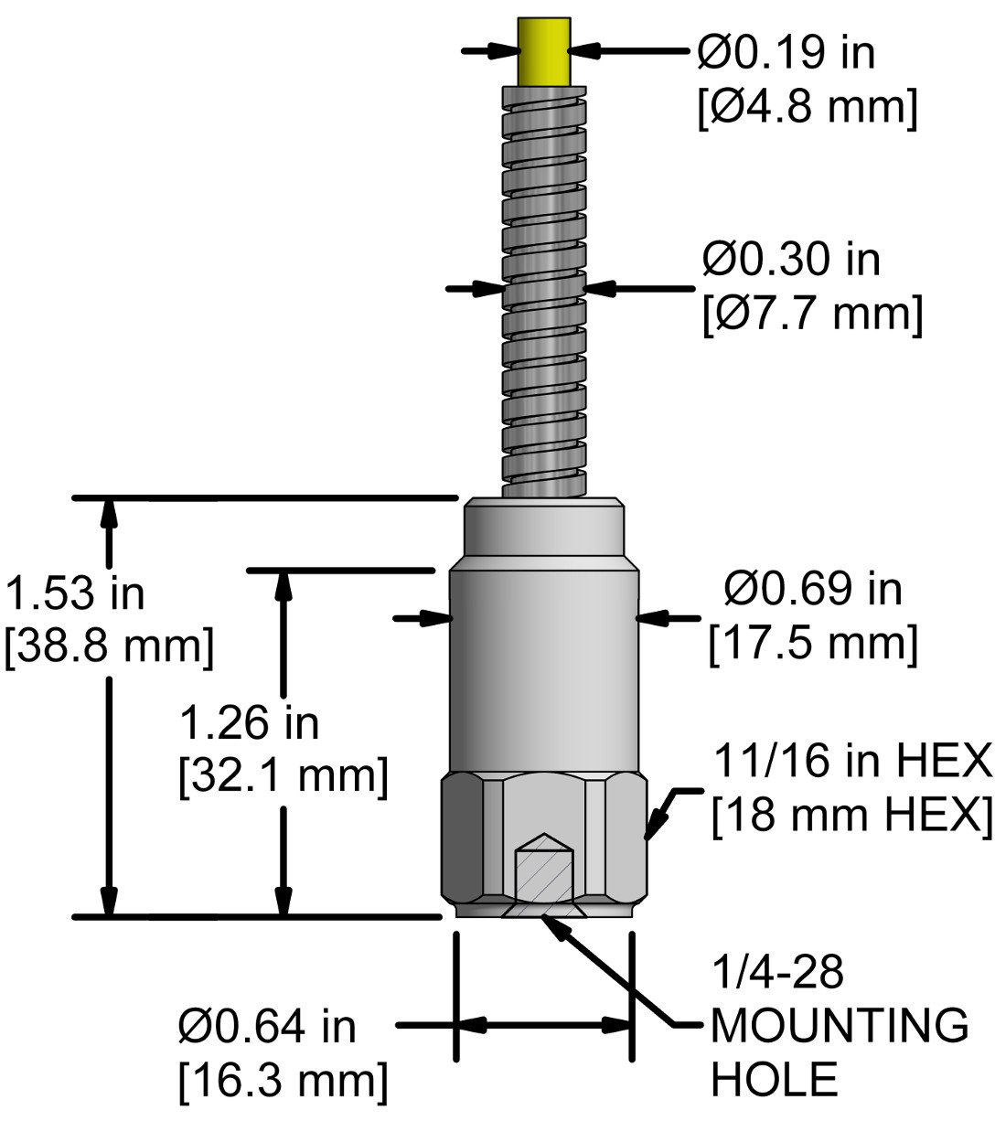
AC214-2D & -7A
2D = CB103 Integral Cable
7A = CB124 Integral Cable
| Conductor | Polarity |
| Red | (+) Signal/Power |
| Black | (-) Common |
| Shield | Cable Drain Wire |
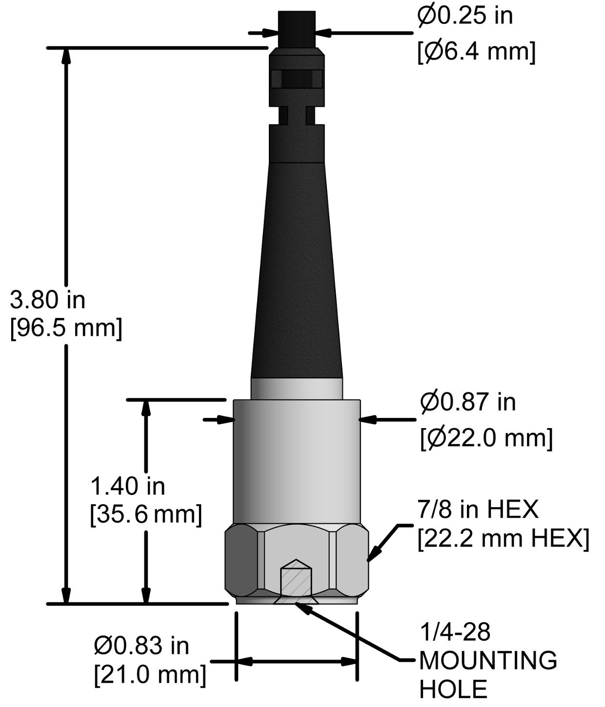
Built To Order
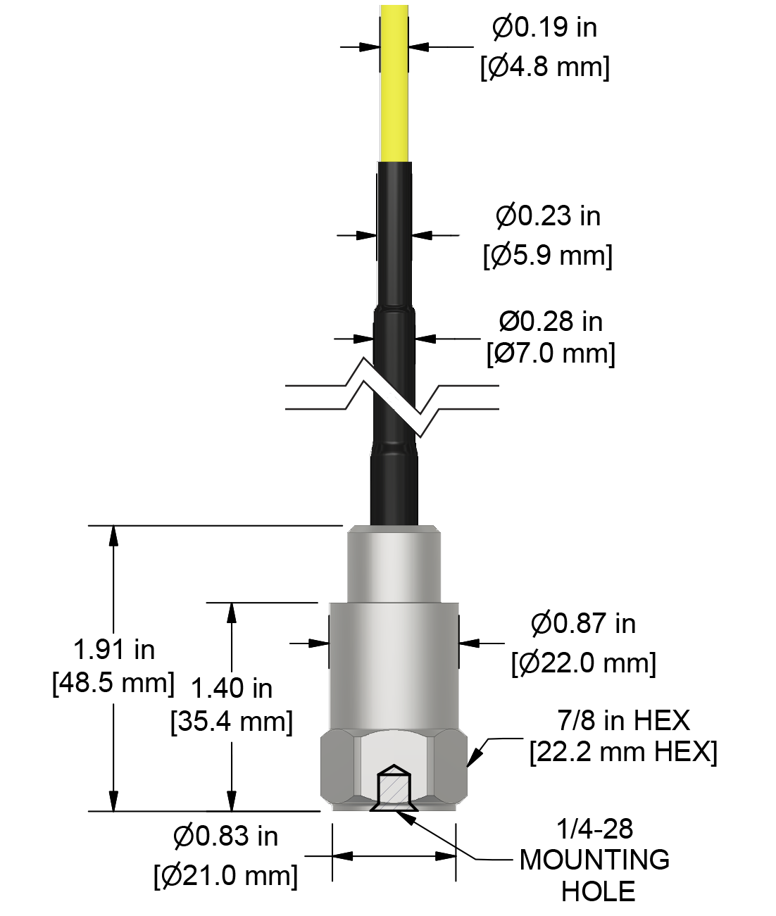
AC214-3D
CB206 Armored Integral Cabel
| Conductor | Polarity |
| Red | (+) Signal/Power |
| Black | (-) Common |
| Shield | Cable Drain Wire |
Built To Order
AC214-6D
CB611 Heavy Duty Armored Integral Cable
| Conductor | Polarity |
| Red | (+) Signal/Power |
| Black | (-) Common |
| Shield | Cable Drain Wire |
Built To Order
AC214-6N
CB111 FEP Jacketed Integral Cable
| Conductor | Polarity |
| Red | (+) Signal/Power |
| Black | (-) Common |
| Shield | Cable Drain Wire |
Built To Order
Typical Frequency Response