
Regulatory Information
CSA 221421
Ex ia IIC T3/T4 Ga
Ex ia I Ma
AEx ia IIC T3/T4
CLI Groups A, B, C, D
CLII Groups E, F, G; CLIII
CLI, Zone 0
Operating Temp Code: T3
Ambient Temp Range = -40 to 121°C
Operating Temp Code: T4
Ambient Temp Range = -40 to 80°C
Control Drawing INS10012
Ex ia IIC T3 -40°C < Ta < +121°C
Ex ia IIC T4 -40°C < Ta < +80°C
1600 ft (488 m) Maximum Allowable
Integral Cable Length
Approved Cabling: CB102, CB103*, CB111, CB190*, CB193*, CB296 (*Approved for Use in T4 Applications Only)
Requires one IS111-1B Intrinsic Safety Barrier
Sira 15ATEX2152X
IECEx SIR 15.0060X
Ex ia IIC T3/T4 Ga
Ex ib IIIC T135°C...T143°C Db
Operating Temp Code: T143°C Db
Ambient Temp Range = -40°C to 121°C
Operating Temp Code: T135°C
Ambient Temp Range = -40°C to +80°C
Ex ia I Ma
Connector Exit Entity Parameters:
Ui = 28 Vdc, li = 120 mA, Pi = 1W, Ci = 0nF, Li = 0µH
Integral Cable Entity Parameters
Ui = 28 Vdc, li = 120 mA, Pi = 1W, Ci = 80.4nF, Li = 336µH
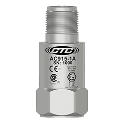
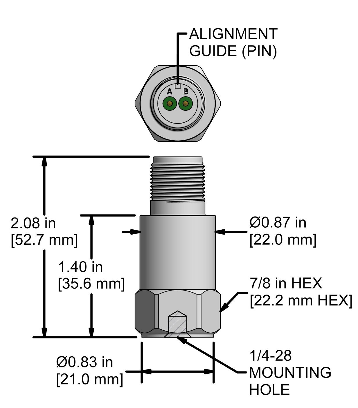
AC915-1A
2 Pin Connector
| Connector Pin | Polarity |
| A | (+) Signal/Power |
| B | (-) Common |

Stock Product
AC915-2C
CB193 Molded Integral Cable
| Conductor | Polarity |
| Red | (+) Signal/Power |
| Black | (-) Common |
| Shield | Cable Drain Wire |

Built To Order
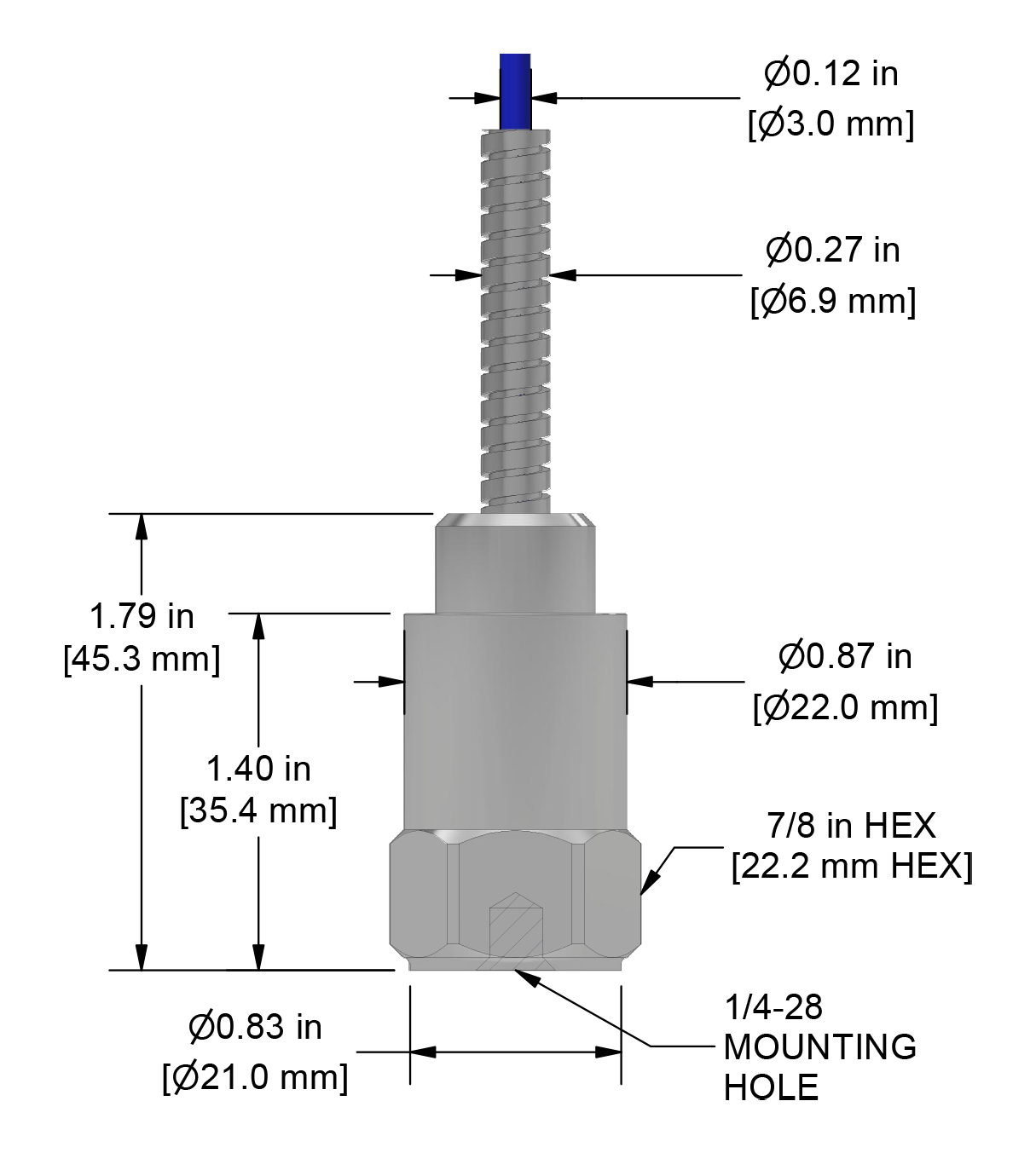
AC915-3C
CB296 Armored Integral Cable
| Conductor | Polarity |
| Red | (+) Signal/Power |
| Black | (-) Common |
| Shield | Cable Drain Wire |

Built To Order
Typical Frequency Response


