Speed/Phase Analysis Hardware Solutions

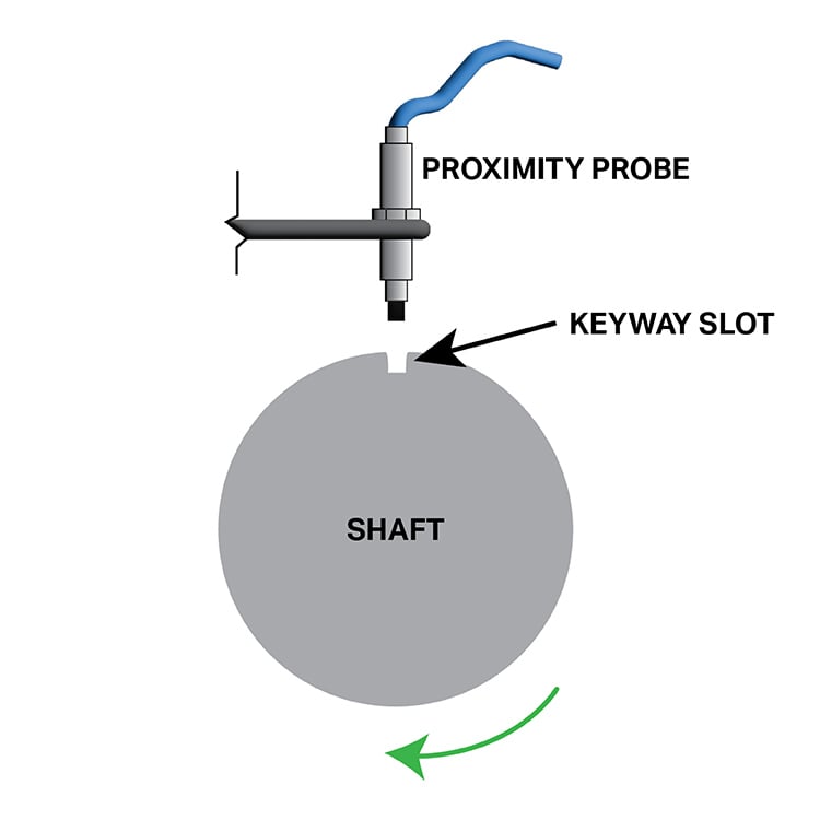
For speed/phase analysis applications, CTC recommends using our PRO Dynamic Voltage Probe Systems. Probes utilized in speed/phase applications should be mounted over the portion of the shaft that has one or more keyways in its rotational path. PRO Proximity Probes used in this manner will produce once-per-revolution or multiple event-per-revolution pulses from a rotating shaft or gear. The PRO Proximity Probe System provides data that can be used to trigger a device that generates a digital pulse signal. A third-party device, like a relay, is used to get a pulse signal equivalent to a Bently Nevada™ Keyphasor™ module. PRO Proximity Probe Systems will only provide the displacement data that will show when the keyway passes by the probe tip; it will not generate any kind of signal itself.
PRO Proximity Probe Systems with Voltage Drivers can be used with Bently Nevada™ Keyphasor™ 3500, or equivalent third-party models, and external diagnostic equipment to measure shaft rotative speed and vector parameters such as 1x vibration amplitude and phase. The input signal range of these keyway modules is +0.8 V to -21.0 V and they are designed to take in dynamic voltage data from standard proximity probes. The real-time displacement measurements from these probes give the modules an indication of when the keyway(s) on the shaft travels in front of the proximity probe.

The figure above shows the real-time displacement data from a voltage probe mounted over a keyway in a rotating shaft. In this example, you can see two displacement spikes that occur as the keyway rotates in front of the probe tip. The data shows two full rotations of the shaft since there are two spikes and only one keyway in the shaft. If the proximity probe set was used with a third-party proximity probe speed/phase module, it would produce a digital pulse signal each time one of these displacement spikes occurs. The time between pulses can be utilized to calculate the speed of the shaft. When this data is used simultaneously in conjunction with two radially-mounted probes (on a different part of the shaft not over the keyway) it allows the analyst to perform phase analysis. Phase analysis allows the analyst to detect which direction during a shaft's rotation that vibration and position changes are occurring.

For applications not utilizing a third-party proximity probe speed/phase module, dynamic voltage probe systems can still provide speed and phase measurements when mounted over a keyway. Depending on the DAQ system and software being used, an analyst will have to set certain amplitude thresholds to trigger a "keyway pulse" when the voltage probe system detects a keyway. For example, if an end-user has a shaft with a 0.5 mm keyway, they should set their "Keyphasor™ pulse signal" to trigger at 0.5 mm so a speed/phase pulse will only occur when the keyway passes through the measurable field of the probe system.

