JOURNAL BEARING MONITORING GUIDE
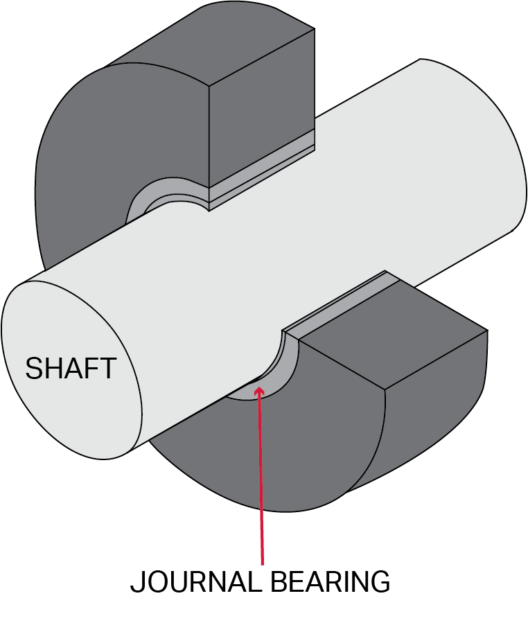
A Journal Bearing, or Fluid Film/Sleeve Bearing, is a type of bearing in which the shaft is suspended in a pressurized regime of oil. These are used on very large or powerful rotating machines to provide damping of the vibration to pass through critical speeds and suppress instabilities caused by loads or natural frequencies of the housing. This damping of the vibration protects the rest of the production line from the extreme force generated by the rotating element, but it also makes it difficult for regular accelerometers to get accurate vibration data of the shaft while mounted on the machine housing.
Inductive Proximity Probes (Eddy Current Probes) are non-contact displacement sensors used to determine the absolute displacement between the tip of a sensor and a conductive target material. These probes use the fluctuations induced in an electromagnetic field generated by the probe system to determine the bearing shaft position relative to the bearing casing and the dynamic vibration of the rotating shaft. Industrial Proximity Probes are most commonly used in petrochemical and energy production, specifically in turbines and reciprocating compressors that utilize Journal Bearings.
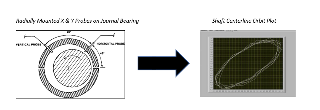
Proximity Probes provide very accurate information on the position and vibration of the journal bearing shaft relative to the rest of the machine housing. For typical radial condition monitoring applications, two probes will be mounted perpendicular to the shaft 90° apart from one another to measure the X and Y axes. The vibration of the shaft will be measured as a variable DC voltage that simulates an AC vibration signal.
Using this position/vibration data from both axes, analysts can create an orbit that can be used to measure the total vibration of the shaft’s centerline as it rotates in the bearing sleeve. An orbit will provide the peak-to-peak displacement and direction of the vibration relative to the shaft centerline. The location of the shaft centerline within the bearing sleeve can also be measured with radially mounted probes. The DC portion of the voltage signal is proportional to the space between the probe tip and shaft surface. This measurement is critical in knowing the location of the shaft within the bearing housing and preventing metal contact between the shaft and bearing sleeve which could have catastrophic results.
What is a Complete Proximity Probe System?
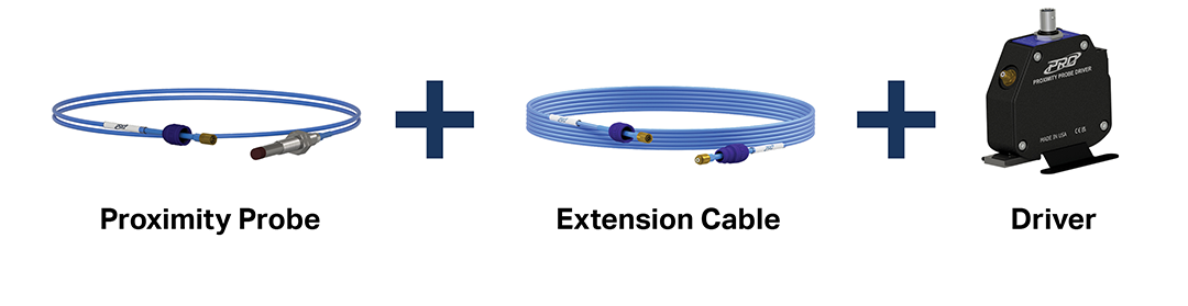
Eddy Current Proximity Probe Systems are an effective way to monitor Journal Bearings. A complete Proximity Probe System consists of a Proximity Probe, Extension Cable, and a Proximity Probe Driver.
Standard vs. Hazardous Rated Systems
All PRO Line Proximity Probe Systems are available in both standard and hazardous-rated configurations.
Optional regulatory approvals for hazardous-rated systems include CSA, ATEX, IECEx, and CE. Please note - these certifications require the intrinsically safe barrier driver to be mounted in a NEMA 4x and/or IP6x enclosure.
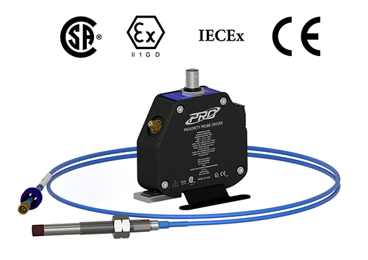
Selecting Your Ideal Proximity Probe System
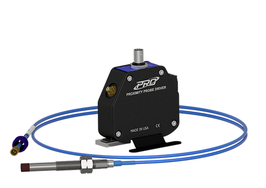
CTC offers a complete line of proximity probe systems designed, built, and tested to endure prolonged use in the harshest industrial environments. PRO Line Proximity Probe Systems are available in FFV, 8 mm, 11 mm, and 25 mm systems. The variety of probe sizes offered allows for accurate and precise displacement measurements as well as shaft speed/phase analysis. Complete PRO Line Proximity Probe Systems are compatible with all standard condition monitoring software, including Alta Solutions, Bently Nevada, and TWave software.
Probe Tip Sizes
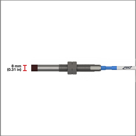
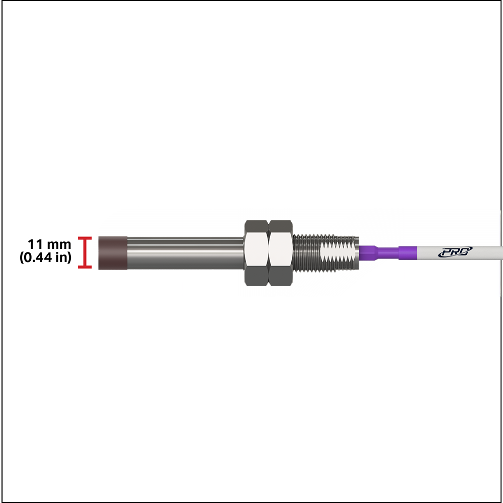
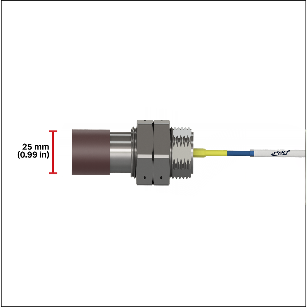
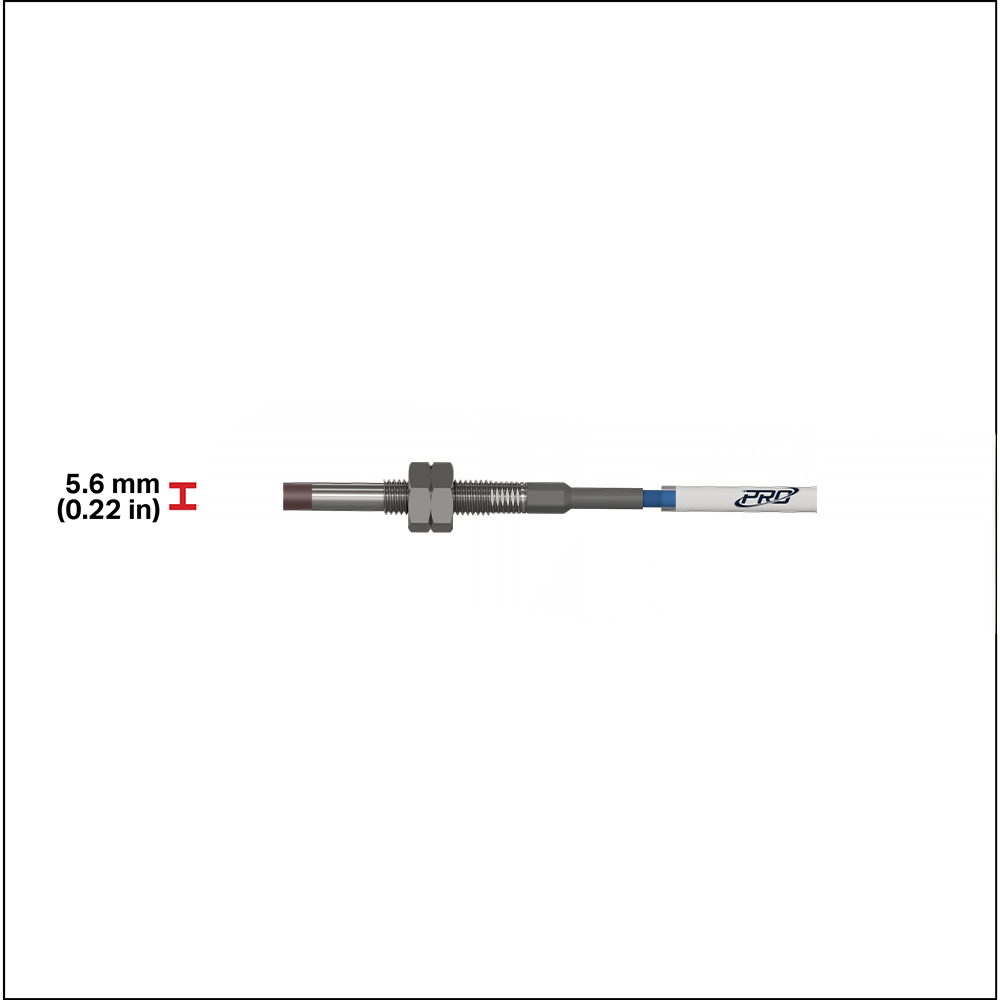
FFV Probe Tip
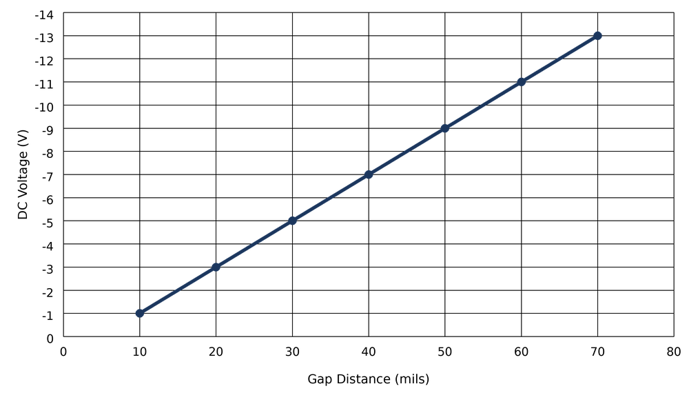
For displacement gaps of 10-70 mils
Output Sensitivity:
-200 mV/mil (-7.87 V/mm)
Note - FFV probes may be used for any applications within their linear range when clearance is an issue. They are the only probes we recommend for shafts with a diameter less than 2 inches. They are also used for many general purpose applications for larger shafts.
System Length
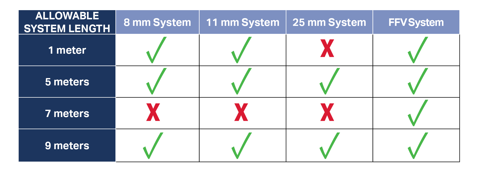
The length of a proximity probe plus extension cable must equal one of the system lengths allowed for your probe size selection.
Refer to the chart below to determine the system length that is best for your application:

Other Important Considerations
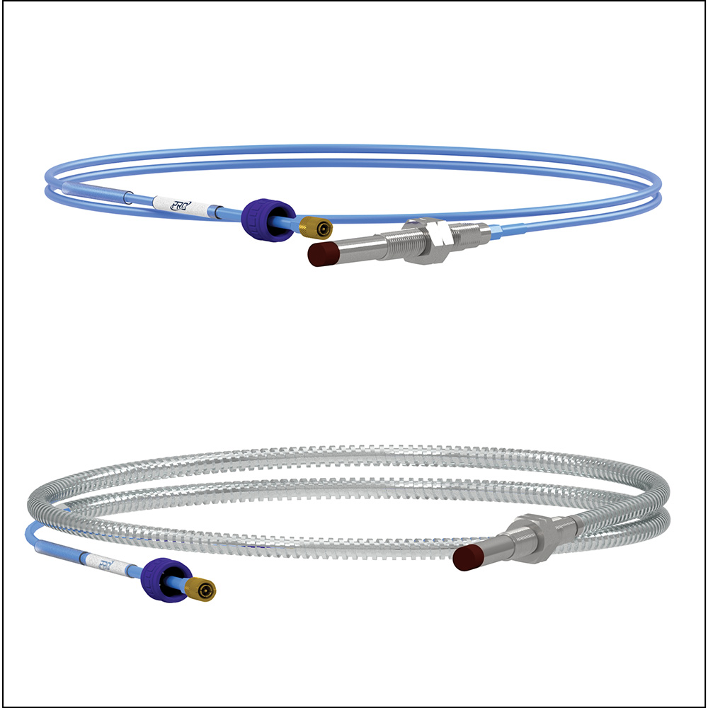
Cable Jacket
Standard FEP Jacket or Armor Jacket available
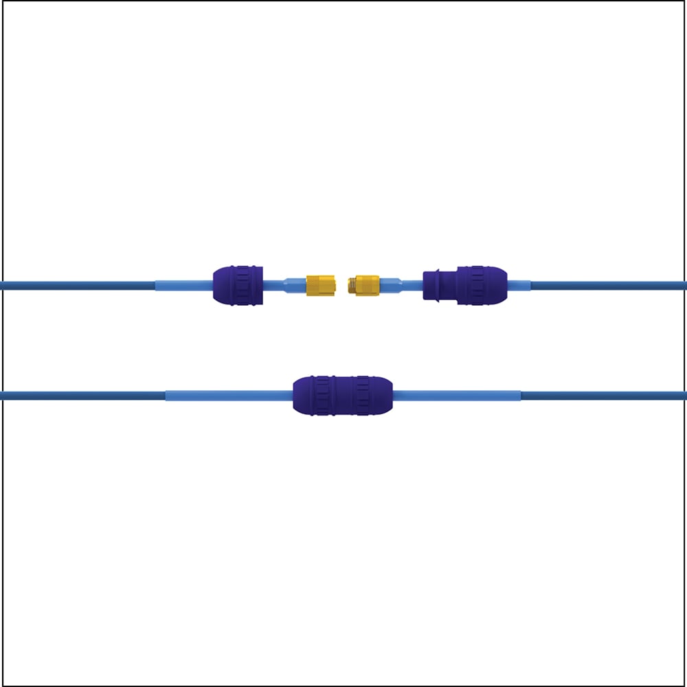
Connector Protectors
Required for hazardous applications
Provide an added layer of durability for the connection between your probe and extension cable
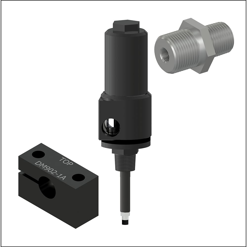
Mounting Style
Standard internal and external brackets and bushings as well as external housing for "reverse mount" probe systems available
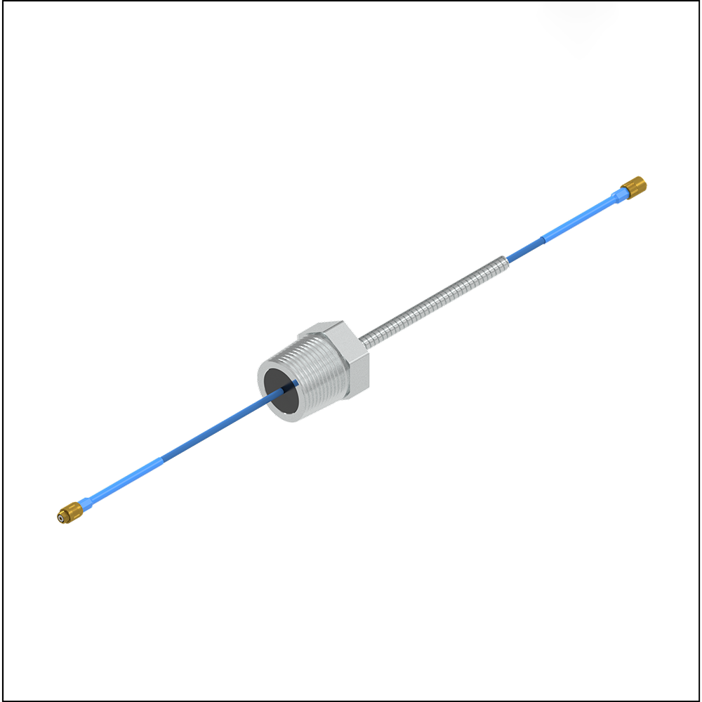
Single-sided NPT fitting with factory-installed proximity probe extension cables, rated to 400 PSI for high pressure applications.
Proximity Probe Mounting
In this method, the probe will be threaded into the bushing, bracket, or bored-out hole in the machine housing and screwed down until the probe tip is close to the target shaft. A non-metallic feeler gauge is required and should be the size of the desired gap between the probe and the target. For example, 50 mils is a common gap selection for 8 mm probe systems since it sits near the midpoint of the system's linear range of 10-80 mils. The probe should be carefully turned into the housing until it is lightly touching the feeler gauge. Once the probe gap is set, the probe should be locked into place with the locknuts on the probe casing.
The first step for this method is to connect the Proximity Probe to its extension cable and driver. Apply -24V to the driver and connect a digital multimeter to the voltage output terminal. Insert the probe into the tapped mounting hole. As the probe tip is threaded through the hole, the sensor's output voltage will remain low or give a false reading because it is sensing the surrounding materials of the machine housing. As the probe extends through the housing, the output voltage will increase to its maximum point and then decrease as it approaches the observed surface. The output voltage from the probe system should correspond with the calibration curve that is published on the calibration certificate. Use the linearization table on the calibration certificate to gap the probe to the desired distance.
Proximity Probe Driver Selection
PRO Voltage Drivers also come supplied with a three-wire output terminal block to connect to a protection system.
CTC also offers four-wire Proximity Probe Drivers with a scaled 4-20 mA output proportional to either gap displacement, radial vibration, and axial position.
The dynamic voltage signal is available on all proximity probe drivers via the BNC Jack located on the unit.
Reference the following diagrams to determine the best driver selection for your application:
CTC offers a wide variety of proximity probe driver configurations. Regardless of configuration, all PRO Line drivers come equipped with a buffered BNC that allows the user access to unfiltered voltage data.
Voltage Drivers
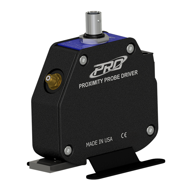
The voltage driver has a dynamic voltage output that is compatible with industry-standard continuous vibration monitoring systems and is the format specified in API Standard 670. The dynamic voltage output is proportional to the DC gap between the target material and the probe tip.
Typical Response Curve - FFv Voltage Driver (10 - 70 mils)
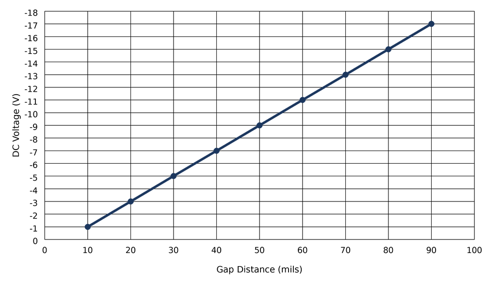
Typical Response Curve - 8 mm Voltage Driver (10 - 90 mils)
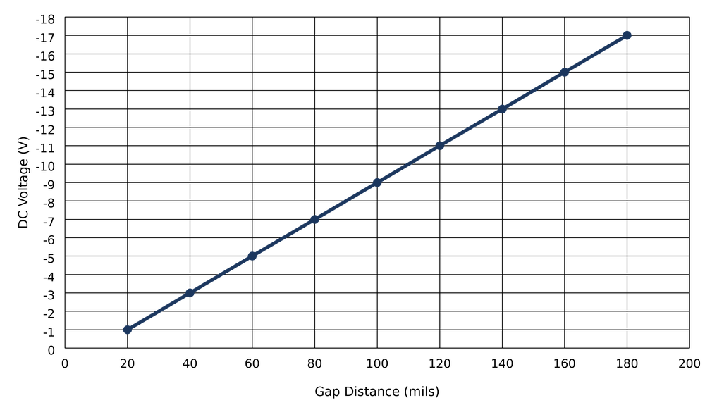
Typical Response Curve - 11 mm Voltage Driver (20 - 180 mils)
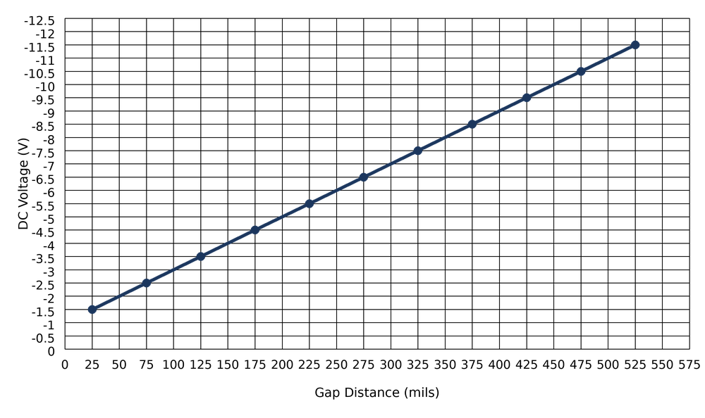
Typical Response Curve - 25 mm Voltage Driver (25 - 525 mils)
4-20 mA Drivers
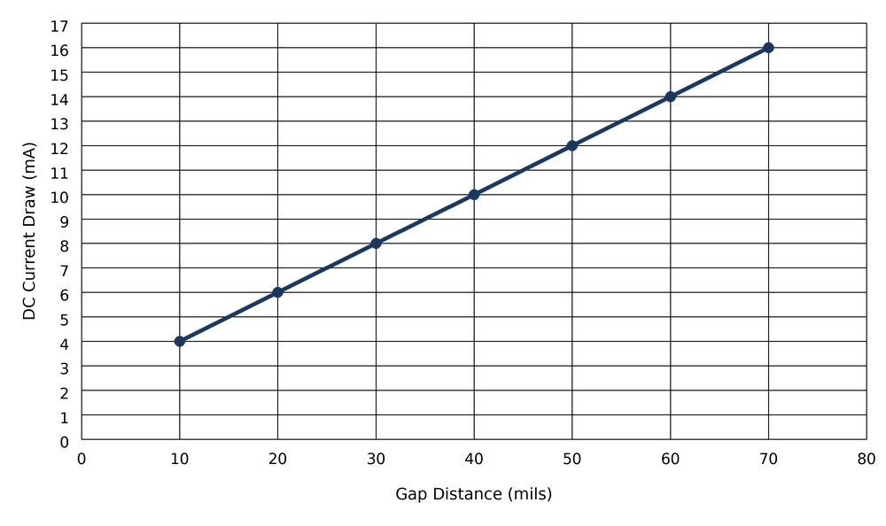
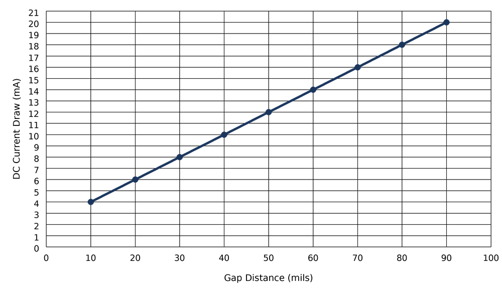
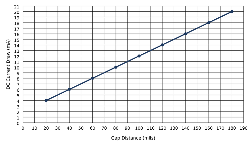
This Current driver option provides a current loop signal, in addition to the voltage output as seen on the voltage drivers, that is propotional to the DC gap distance between the probe tip and the target.
4-20 mA DRIVERS PROPORTIONAL TO DC GAP
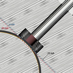
Probe showing proportional output for the 4-20 mA signals.
With shaft surface at 50 mils, 4-20 output is 12 mA.
If the gap increases to 70 mils, 4-20 output will be 16 mA.
Note: Current will be 180° out of phase for 4-20 mA drivers.
The output is linear across the calibrated probe range (e.g., 10 - 90 mils), with 4 mA and 20 mA corresponding to the minimum and maximum limits of that lienar range, respectively. The midpoint of the gap range corresponds to approximately 12 mA.
Typical Response Curve - FFv 4-20 mA Driver (10 - 70 mils)
Typical Response Curve - 8 mm 4-20 mA Driver (10 - 90 mils)
Typical Response Curve - 11 mm Voltage Driver (20 - 180 mils)
Please note, 25 mm 4-20 mA Drivers are not currently offered
RADIAL DRIVERS
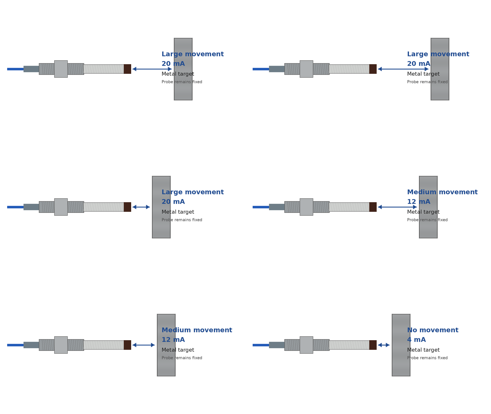
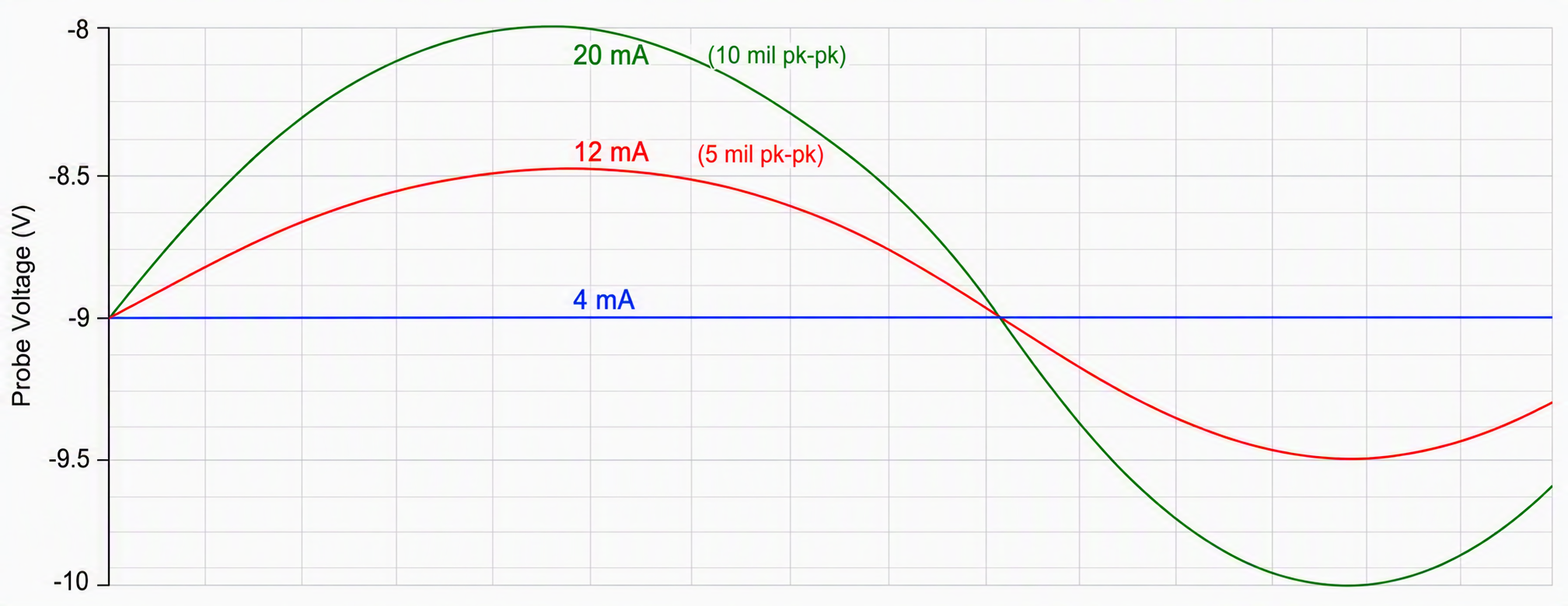
This Current driver option provides a current loop signal, in additional to the voltage output as seen on the voltage drivers, proportional to peak-to-peak shaft displacement (vibration) in mils. The probe must be set to its midpoint gap (nominal DC voltage, typically ~–9 V), such that the 4–20 mA output represents dynamic motion about this average position.
The "Full Scale Range" specifies the pk–pk displacement corresponding to 20 mA. For example, a 0–5 mil pk–pk unit will output:
- 4 mA at 0 mil pk–pk (no vibration)
- 12 mA at 2.5 mil pk–pk
- 20 mA at ≥5 mil pk–pk
Note: This output is not valid for low-frequency motion (typically below 50 Hz), where dynamic measurement accuracy is reduced.
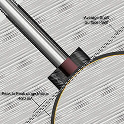
In radial applications, the probe drivers select the average shaft surface distance and the 4-20 is proportional to the overall peak-to-peak vibration in mils around the average surface of the shaft. Note, phase is not applicable for radial drivers
AXIAL DRIVERS
This Current driver option provides a current loop signal, in addition to the voltage output as seen on the voltage drivers, proportional to axial displacement relative to a defined zero (reference) position.
The midpoint of the output (12 mA) corresponds to the defined zero position (typically near the nominal gap voltage, e.g., ~–9 V). The output then scales linearly with displacement away from this reference:
For a unit specified as "0 ±25 mils":
- 4 mA corresponds to –25 mils (movement toward the probe)
- 12 mA corresponds to 0 mils (reference position)
- 20 mA corresponds to +25 mils (movement away from the probe)
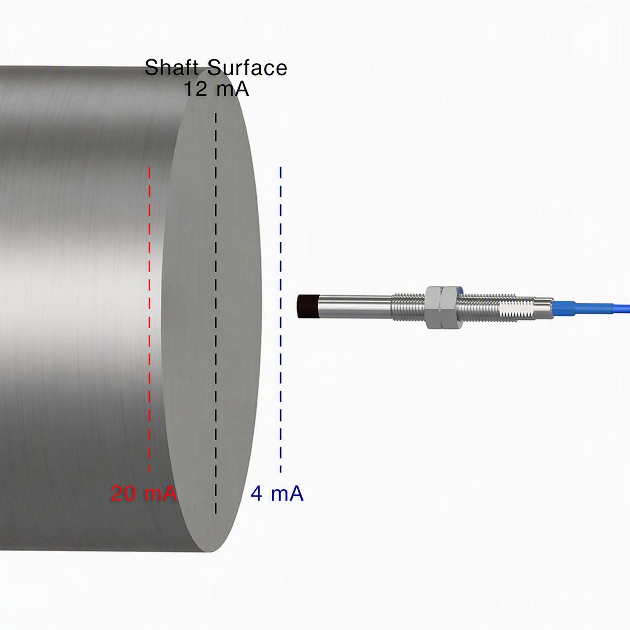
In the thrust position the probes auto-range to the face of the shaft or thrust collar and the 4-20 is proportional to the positive or negative vibration away or toward the probe, as shown.
Note, current will be 90 degrees out of phase for axial driver.
The midpoint of the output (12 mA) corresponds to the defined zero position (typically near the nominal gap voltage, e.g., ~–9 V). The output then scales linearly with displacement away from this reference:
For a unit specified as "0 ±25 mils":
- 4 mA corresponds to –25 mils (movement toward the probe)
- 12 mA corresponds to 0 mils (reference position)
- 20 mA corresponds to +25 mils (movement away from the probe)
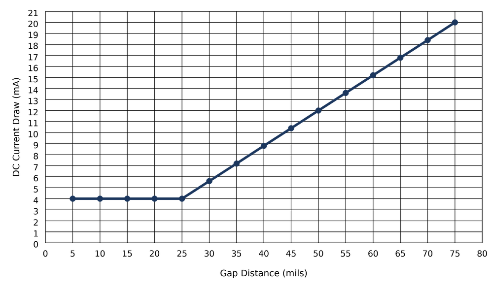
Typical Response Curve - FFv Axial Driver (5 - 75 mils)
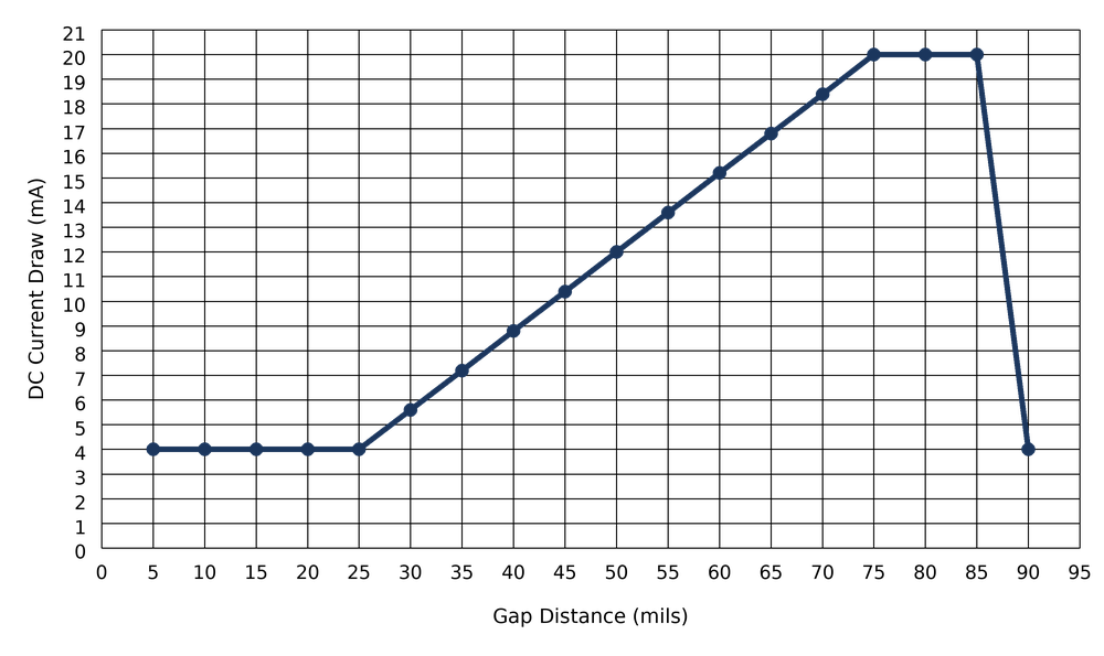
Typical Response Curve - 8 mm Axial Driver (5 - 90 mils)
Typical Response Curve - 11 mm Axial Driver (20 - 180 mils)
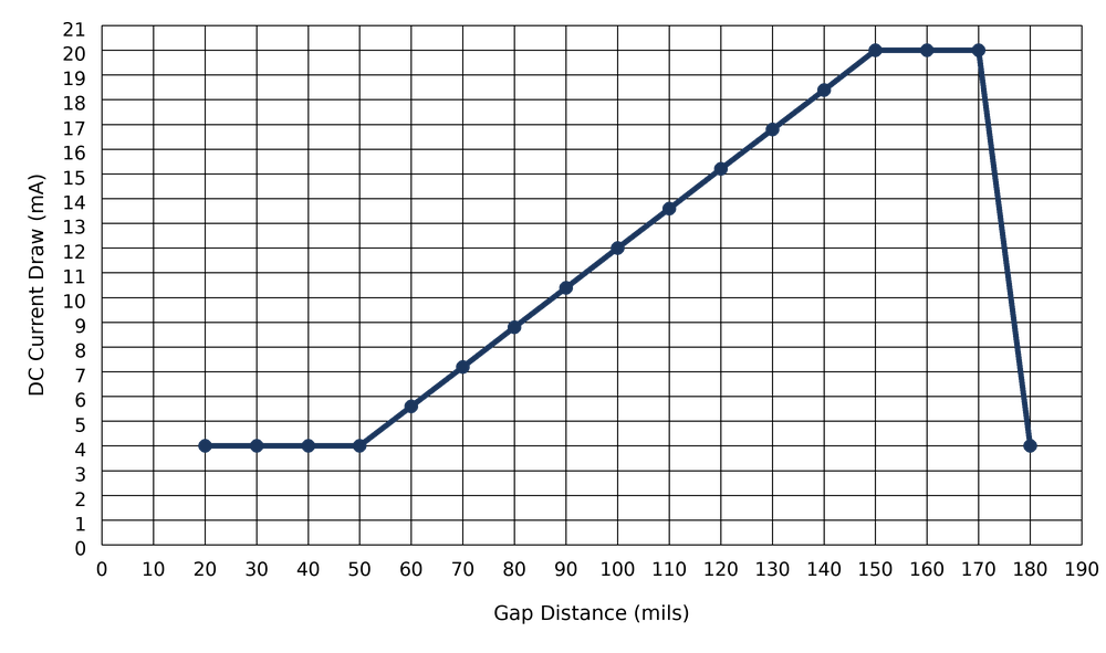
The output is only guaranteed to be linear within this specified ± range. Outside of this range, current signal performance is not defined.
Proximity Probe Driver Enclosures
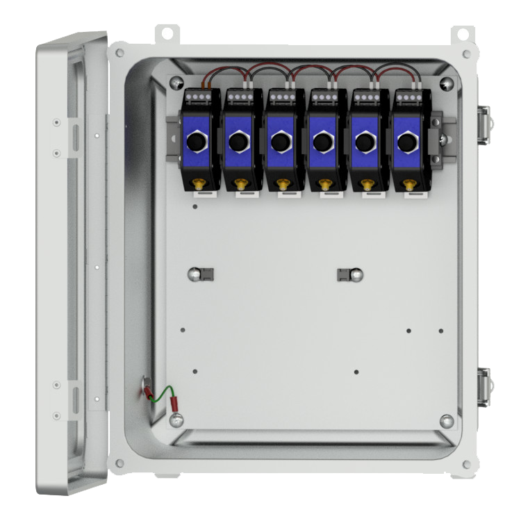
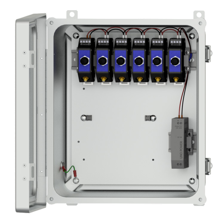
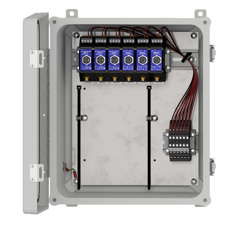
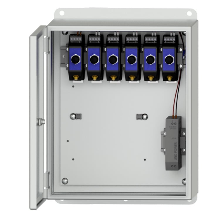
CTC offers our PXE Proximity Probe Driver Enclosures in both fiberglass and stainless steel options. PXE Enclosures are NEMA 4X rated to ensure your proximity probe drivers are protected from dirt, dust, oil, and water.
24V power supply and/or terminal blocks are also available as configurable options for the PXE150 and PXE250.