Success Story: Early Detection of Shaft Runoff & Wear in Belt-Pulley Driven Fan
A special thank you to our approved software integrator ASCRIBO for this success story
Click here to download the printer-friendly pdf version of Success Story: Early Detection of Shaft Runoff & Wear in Belt-Pulley Driven Fan
Introduction
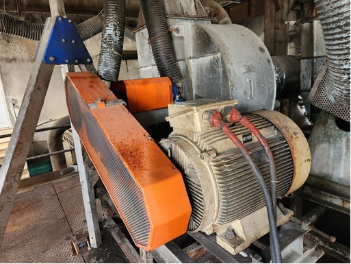
A belt-pulley driven fan at a paper mill began exhibiting elevated vibration levels, particularly in the vertical axis. Initial assumptions pointed to bearing issues, and 1311 ETN9 self-aligning ball bearings were considered due to their tolerance for misalignment and shaft curvature. However, the root cause was not immediately clear.
Location / Application
Paper Mill / Belt-Pulley Driven Fan
Technology Used
ASCRIBO ABLE System + CTC ConnectSensTM Wireless Sensors and ConnectBridgeTM Wireless Gateway:

Vibration Analysis
The fan was continuously monitored by ASCRIBO's ABLE System powered by CTC Connect WS300 Series Sensors and ACCESS360 Gateway. The system collected triaxial vibration data hourly and analyzed it using ASCRIBO's advanced unsupervised learning algorithms.

Triaxial vibration data was collected on an hourly basis from the pulley side bearing of this vacuum fan.

While the overall vibration level in the fan pulley side bearing was at a level between 10-15 mm/s, a systematic increase was observed in the vertical axis which reached up to the levels of 20-25 mm/s.

Lack of an increase in bearing failure trends also supported the idea that there may be runout in the shaft.
An increase in overall vibration levels (OVL, mm/s) along the vertical axis of the equipment was observed. This prompted an evaluation of potential causes, including shaft oscillation or bending due to diameter loss, bearing wear, and out-of-tolerance gaps within the bearing assemblies.
Among these possibilities, the most likely cause was identified as shaft wear and runout failure. This conclusion was supported by two key findings:
1. No signs of degradation were detected in any bearing subcomponents
2. The ABLE System's component-specific "Vibration Source Analysis" indicated that the dominant vibrations originated from the shaft

As can be seen from the "Vibration Source Analysis" graph, the distribution rate of the vibration signal is observed to be dominant compared to the bearing and fan blades in the overall distribution.
Subsequently, the equipment was taken out of service for maintenance. Post-maintenance inspection confirmed the diagnosis: Shaft wear and runout failure.
The pulleys, shaft, and bearings were replaced. Following the replacement, a decrease in the overall vibration level (mm/s) was observed.
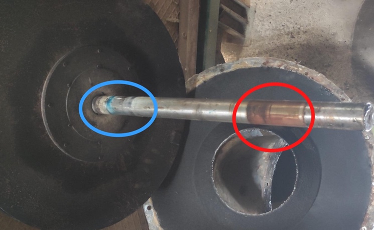
After disassembling the shaft in the equipment that rotates at 3000 rpm, traces of wear caused by runout are seen at two endpoints.

Due to the shaft runout, the bearing was strained and oil deterioration was observed. After washing and cleaning, no roughness or burring was detected on the rings.
_________________________________
Learn more about getting started with ASCRIBO + CTC Connect