11 MM PROXIMITY PROBE SETS
CTC’s PRO line of 11mm Proximity Probe Systems offer a larger linear range than standard 8mm or 5mm probe systems. 11mm Proximity Probes are the perfect solution for applications requiring a measurement range over 80 mils (2mm).
Whether you're in the power generation, oil and gas, or industrial manufacturing, our proximity probe sets are sure to meet your needs and compatible with all standard condition monitoring software, including Alta Solutions, Bently Nevada, TWave, and more.
Our PRO Line proximity probes sets are made with the most durable material possible to protect our advanced technology, ensuring a long lifespan even in the harshest environments. With our easy-to-use website, you can customize your probe set to your application's exact needs.
NEW - Custom Calibration Materials
Looking for a unique custom calibration material? We can create a custom target for you.
Requirements:
» $2,500 NRE fee (discount exempt)
» Customer must supply the material for CTC to machine (CTC will provide required dimensions once the project is initiated)
» Initial order requirement of 10 proximity probe drivers calibrated to that target, with no MOQ on subsequent orders
Contact [email protected] to get started with your custom calibration material.
Need help knowing where to start? Scroll down to see our helpful system diagrams to select the right option for your application.


HOW TO CHOOSE YOUR PROXIMITY PROBE DRIVER
CTC offers a wide variety of proximity probe driver configurations. Regardless of configuration, all PRO Line drivers come equipped with a buffered BNC that allows the user access to unfiltered voltage data.
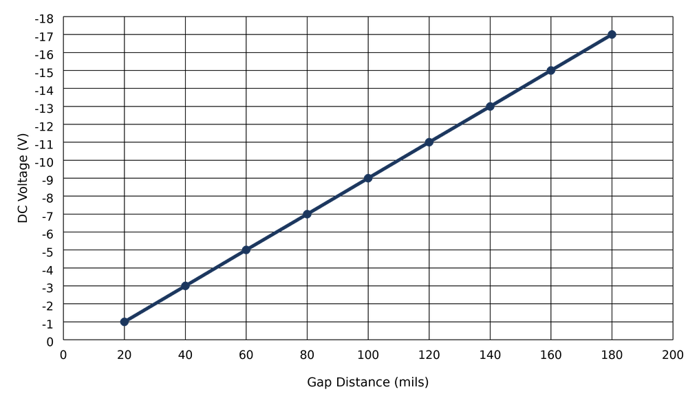
Voltage Driver

The voltage driver has a dynamic voltage output that is compatible with industry-standard continuous vibration monitoring systems and is the format specified in API Standard 670. The dynamic voltage output is proportional to the DC gap between the target material and probe tip.
Typical Response Curve - 11mm Voltage Driver (20 - 180 mils)
4-20mA Drivers
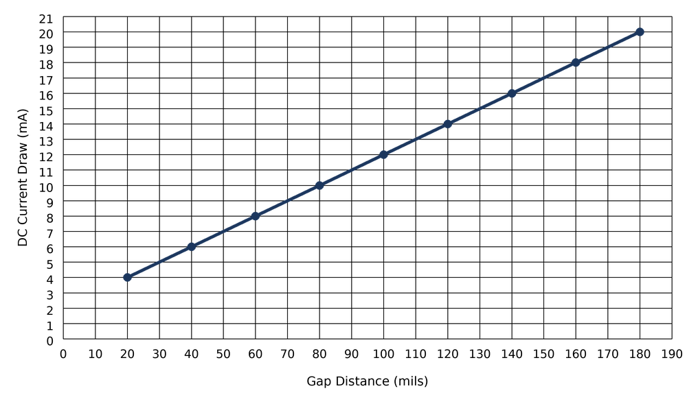
This Current driver option provides a current loop signal, in addition to the voltage output as seen on the voltage drivers, that is proportional to the DC gap distance between the probe tip and the target.
4-20mA Drivers Proportional to DC Gap
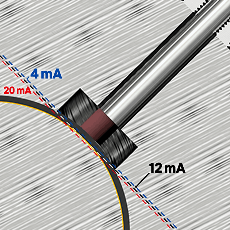
Probe showing proportional output for the 4-20 mA signals.
With shaft surface at 50 mils, 4-20 output is 12 mA.
If the gap increases to 70 mils, 4-20 output will be 16 mA.
Note: Current will be 180° out of phase for 4-20 mA drivers.
The output is linear across the calibrated probe range (e.g., 10 - 90 mils), with 4 mA and
20 mA corresponding to the minimum and maximum limits of that linear range, respectively.
The midpoint of the gap range corresponds to approximately 12 mA.
Typical Response Curve - 11mm 4-20 mA Proportional to DC Gap Driver (20 - 180 mils)
Radial Drivers
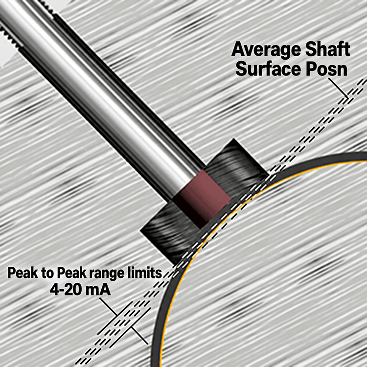
This Current driver option provides a current loop signal, in additional to the voltage output as
seen on the voltage drivers, proportional to peak-to-peak shaft displacement (vibration) in mils. The probe
must be set to its midpoint gap (nominal DC voltage, typically ~–9 V), such that the 4–20 mA output
represents dynamic motion about this average position.
The "Full Scale Range" specifies the pk–pk displacement corresponding to 20 mA. For example, a 0–5 mil pk–pk unit will output:
- 4 mA at 0 mil pk–pk (no vibration)
- 12 mA at 2.5 mil pk–pk
- 20 mA at ≥5 mil pk–pk
Note: This output is not valid for low-frequency motion (typically below 50 Hz), where dynamic measurement accuracy is reduced.
In radial applications, the probe drivers select the average shaft surface distance and the 4-20 is proportional to the overall peak-to-peak vibration in mils around the average surface of the shaft. Note, phase is not applicable for radial drivers
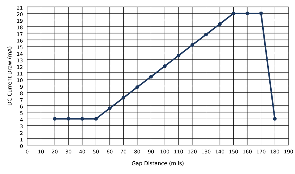
Axial Drivers
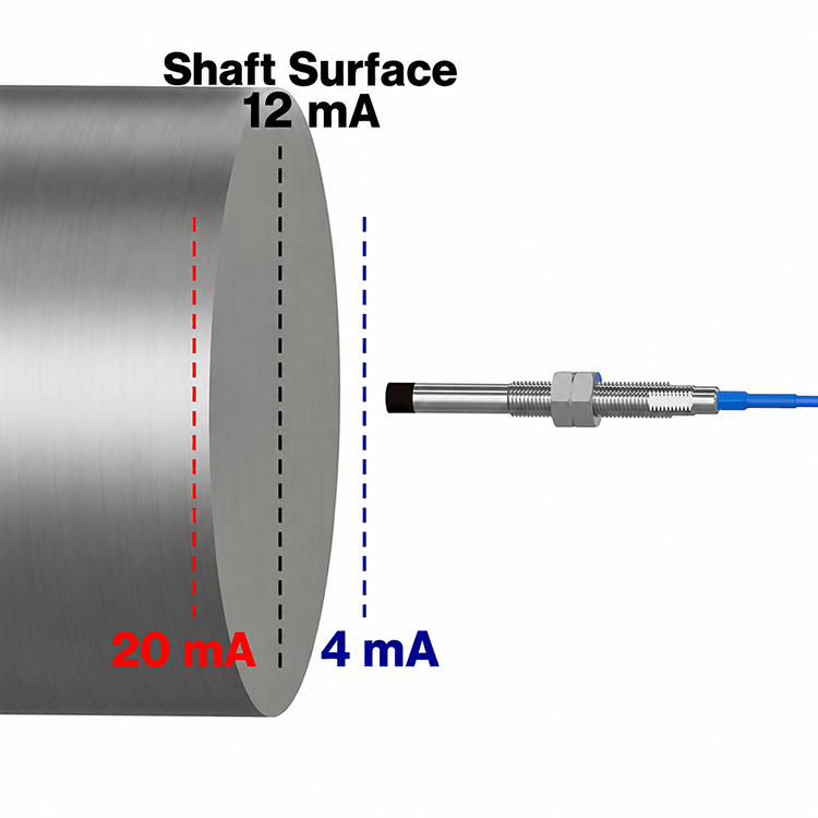
This Current driver option provides a current loop signal, in addition to the voltage output as seen on the voltage
drivers, proportional to axial displacement relative to a defined zero (reference) position.
The midpoint of the output (12 mA) corresponds to the defined zero position (typically near the nominal gap voltage, e.g., ~–9 V).
The output then scales linearly with displacement away from this reference:
For a unit specified as "0 ±25 mils":
- 4 mA corresponds to –25 mils (movement toward the probe)
- 12 mA corresponds to 0 mils (reference position)
- 20 mA corresponds to +25 mils (movement away from the probe)
In the thrust position the probes auto-range to the face of the shaft or thrust collar and the 4-20 is proportional to the positive or negative vibration away or toward the probe, as shown.
Note, current will be 90 degrees out of phase for axial driver.
Typical Response Curve - 11mm Axial Driver (20 - 180 mils)