ROLLING ELEMENT VIBRATION MONITORING GUIDE
Vibration analysis systems are a critical component of any predictive maintenance program. CTC offers everything you need to create a vibration monitoring system for your specific industrial application. Use this guide to familiarize yourself with the major components of a vibration monitoring system and considerations for choosing the most appropriate hardware for your application.
ROLLING ELEMENT VIBRATION MONITORING GUIDE - TABLE OF CONTENTS
Use the links below to navigate to a specific section if desired:
- Creating Your Vibration Monitoring System
- Sensor Considerations
- Sensors Explained
- Choosing Your Accelerometer
- Mounting Hardware Explained
- Cable Assemblies Explained
- Enclosures Explained
- Data Collection Instrumentation Explained
- Other Considerations - Sensor Mounting Techniques
- Other Considerations - Cabling
- Enclosure Comparison
Create Your Vibration Monitoring System
There are five key product categories used in building a complete vibration monitoring system. Follow the flowchart to understand how CTC vibration analysis hardware is combined to deliver accurate data readings:
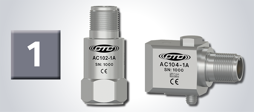
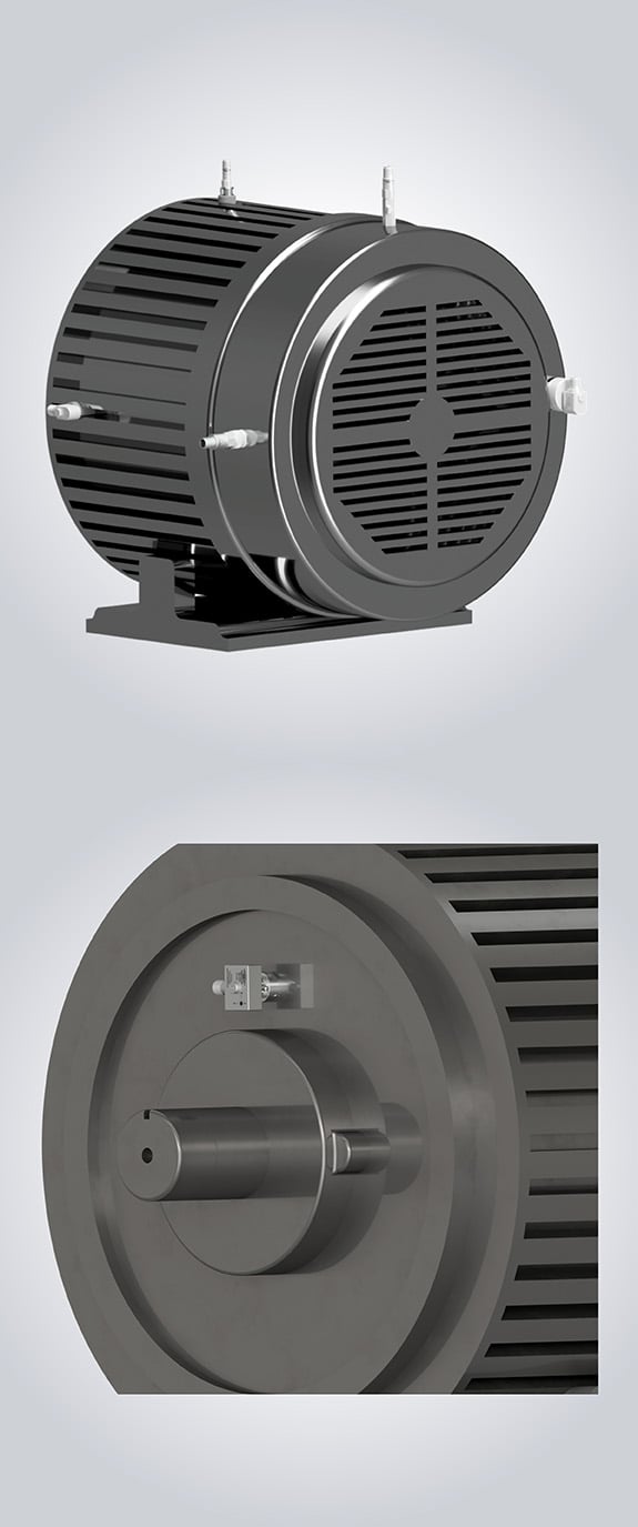
Sensors
Sensors are mounted on rotating equipment to measure machine vibration levels. Vibration is translated by the sensor into an electrical signal which is then sent to a measurement device. CTC offers sensors in single-axis, dual output temperature and vibration, biaxial and triaxial output, and many other options. CTC also offers Loop Power Sensors for 4-20 mA process monitoring.
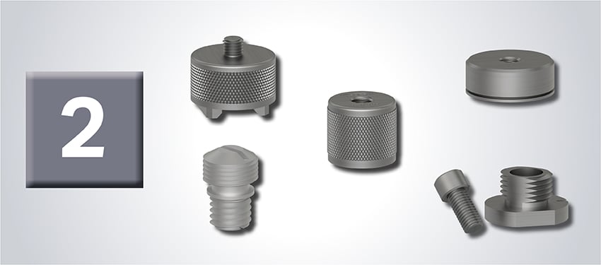
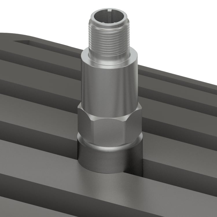
Mounting Hardware
Sensors can be mounted on machines for permanent monitoring and/or portable data collection applications using a variety of hardware, including mounting studs, magnetic bases, adhesive mounting pads, mounting bolts, Zerk mounting adapters, and more.
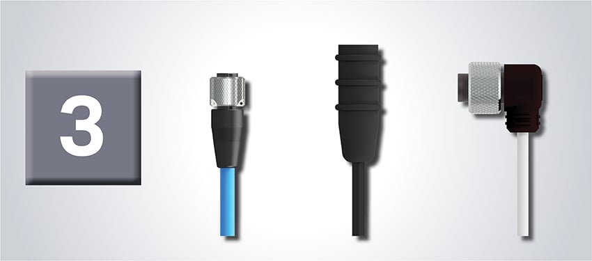
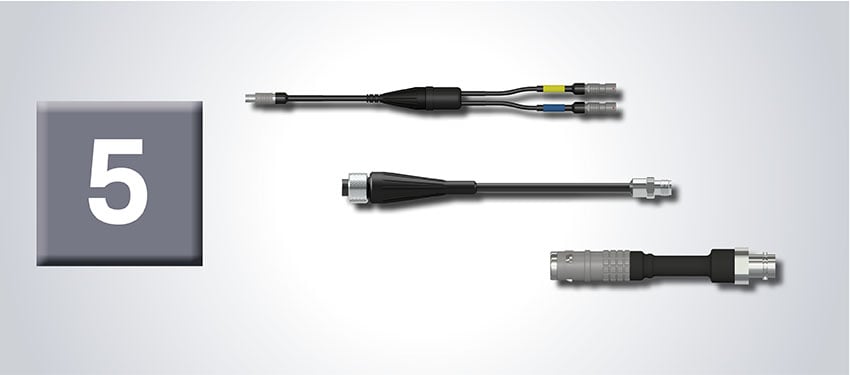
Cable Assemblies
Cables and connectors carry the signal from the sensor to the data collection point. CTC offers the world’s most durable and reliable cables and connectors for permanent monitoring and portable data collection applications. Select the appropriate cable, connector, and termination for the sensor and environment in which your vibration monitoring system will be used.
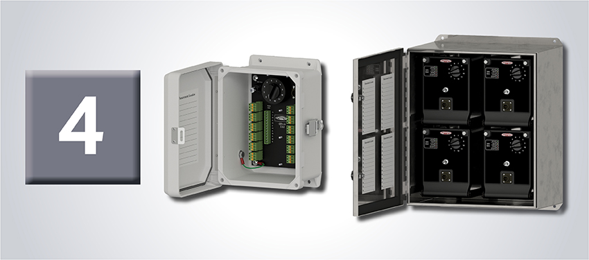
Enclosures
Enclosures create a central data collection point for 1-48 sensors. Our ruggedized enclosures protect your cable terminations from harsh environments to ensure accurate data and are available in fiberglass, stainless steel, and sloped top options.
Data Collection
CTC hardware is compatible with all data collection systems. We make it easy to customize your hardware to your system’s specific needs. We offer a large variety of accessories and the industry’s widest range of data collector connectors and cable adapters.
Exit Type
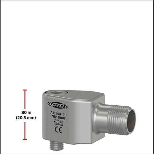
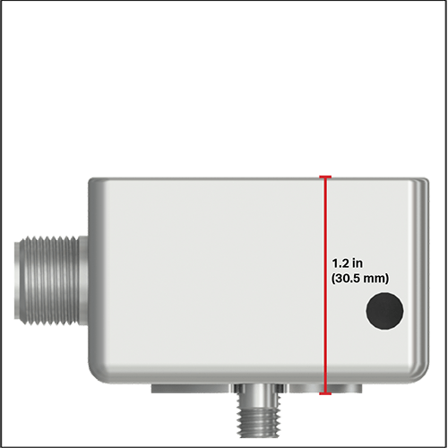
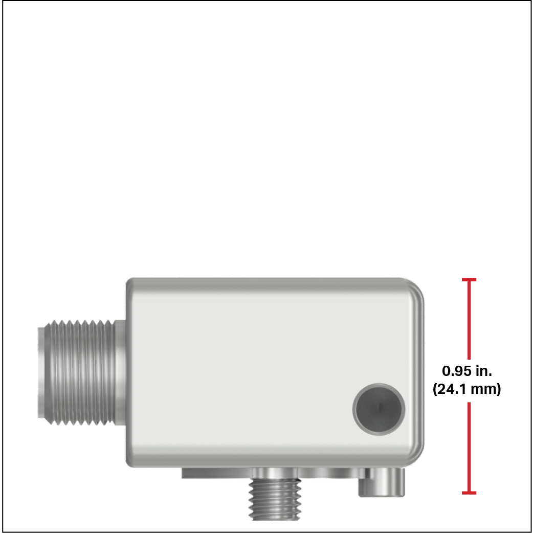
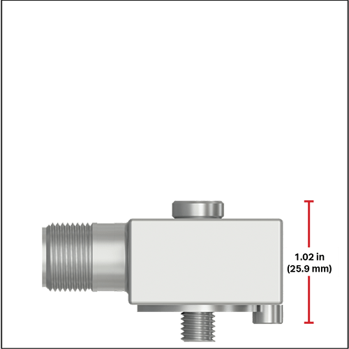
CTC offers most sensors in both top and side exit configurations. Side exit sensors are designed for applications where height clearance is a problem, and a lower profile is needed. Top exit sensors are typically lighter weight than side exit sensors and therefore have a better high-end frequency response.
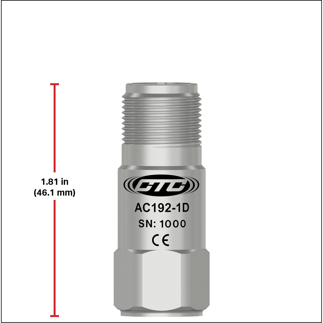
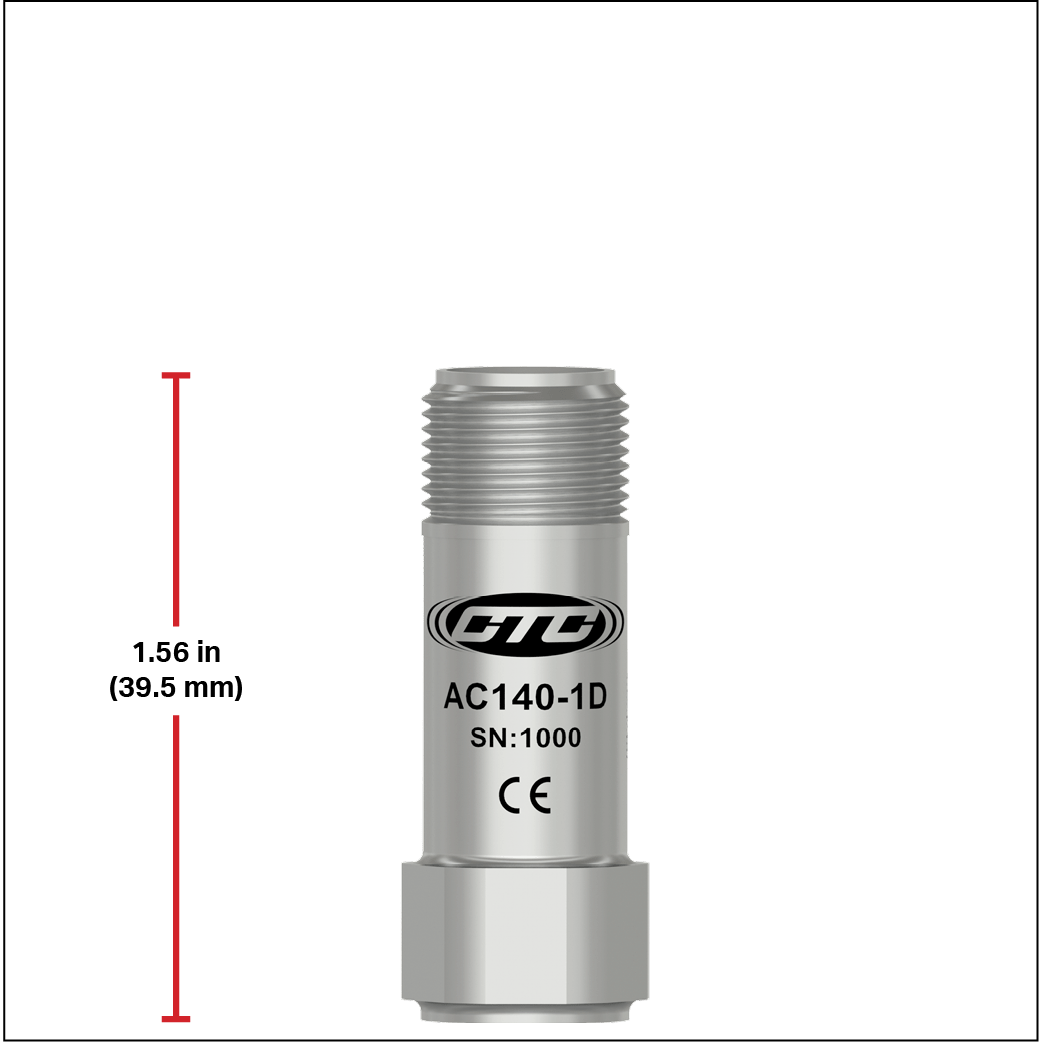
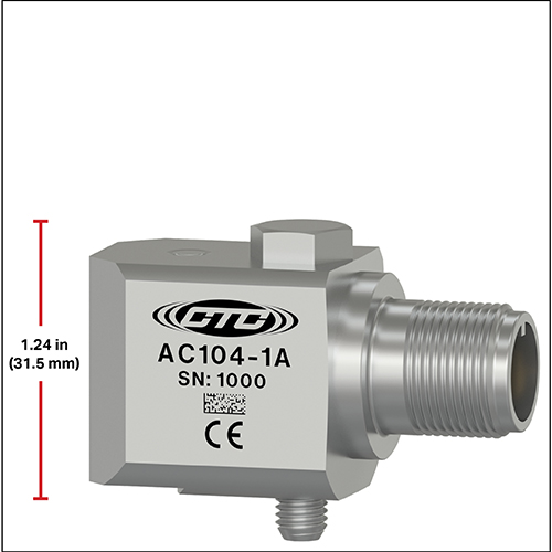
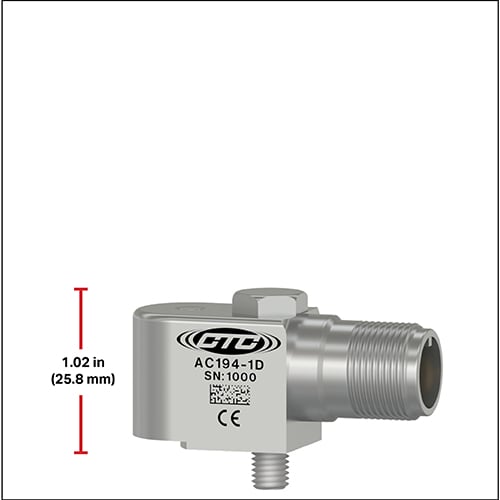
Sensor Case Size
CTC standard-size accelerometers come in the largest variety of sensitivity options, ranging from 10 mV/g to 1,000 mV/g. The larger mass allows for detection at lower speeds. As a result, 500 mV/g and 1,000 mV/g sensors are only available in this case size. CTC compact-size accelerometers are only available in 100 mV/g options. Mini accelerometers are our smallest case size and are great for high-speed applications. The smaller mass and smaller overall weight allow for accurate information on higher speeds.
Single Axis vs. Triaxial Sensors
For the most effective predictive monitoring, all three axes of vibration must be measured to ensure the best understanding of machine health. This requires either three single-axis sensors per bearing or one triaxial sensor. There are many benefits and trade-offs to both.
For permanent monitoring installation, single-axis sensors will provide the highest quality data. However, this requires three single-axis sensors, three mounting spaces, and three cordsets. For triaxial installations, only one sensor, one mounting surface, and one cordset are required. For permanent cable installations where long cable runs are necessary, the cost savings of only running one cable to a Junction Box can be great.
For portable measurements, the largest consideration is time efficiency and human safety. If three axes of measurement cannot be safely reached by the vibration analyst, a triaxial sensor will allow for all measurements to be taken from one location. Additionally, all sensors have a settling time before data can be taken accurately. Since single-axis sensors need to settle on each axis, this increases the time per bearing.
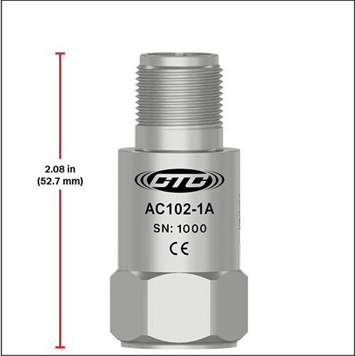
Sensors Explained
Sensors are at the core of any vibration monitoring program.
The industrial accelerometer is the primary vibration sensor needed for rotating equipment utilizing rolling element bearings. The vibrations generated by the machine will be transmitted through the casing of the machine to the base of the accelerometer where the Piezo ceramic reacts with the mass in a shearing mode to produce a charge output. The charge is converted to a voltage and amplified internally in the accelerometer for measurement by the vibration analyzer, data collector, or online monitoring system.
Single Axis Sensor Size Comparison - Top Exit Configuration
Single Axis Sensor Size Comparison - Side Exit Configuration
Triaxial Sensor Size Comparison
Large Size Triaxial
1.2 in. | 30.5 mm
Example Part Numbers:
TXFA331
TXFA331-VE
TXEA331-HT
TXEA331-VE
TSFA333-IV
Sensor Types
Hover over each image to learn more
SINGLE AXIS ACCELEROMETERS
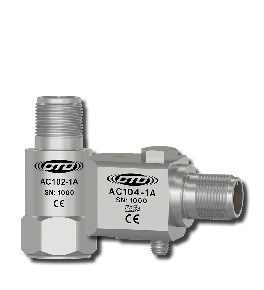
Single Axis Accelerometers
Measure vibration along one axis (X, Y, or Z). Ideal for portable or permanent applications.
BIAXIAL ACCELEROMETERS
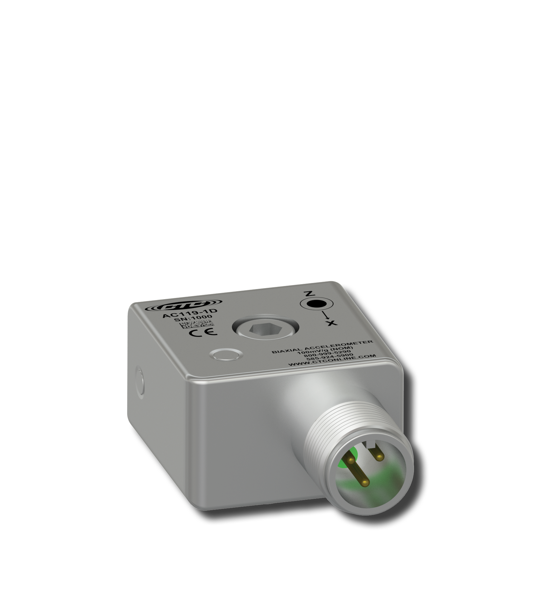
Biaxial Accelerometers
Measure vibration along the X and Z axis.
TRIAXIAL ACCELEROMETERS
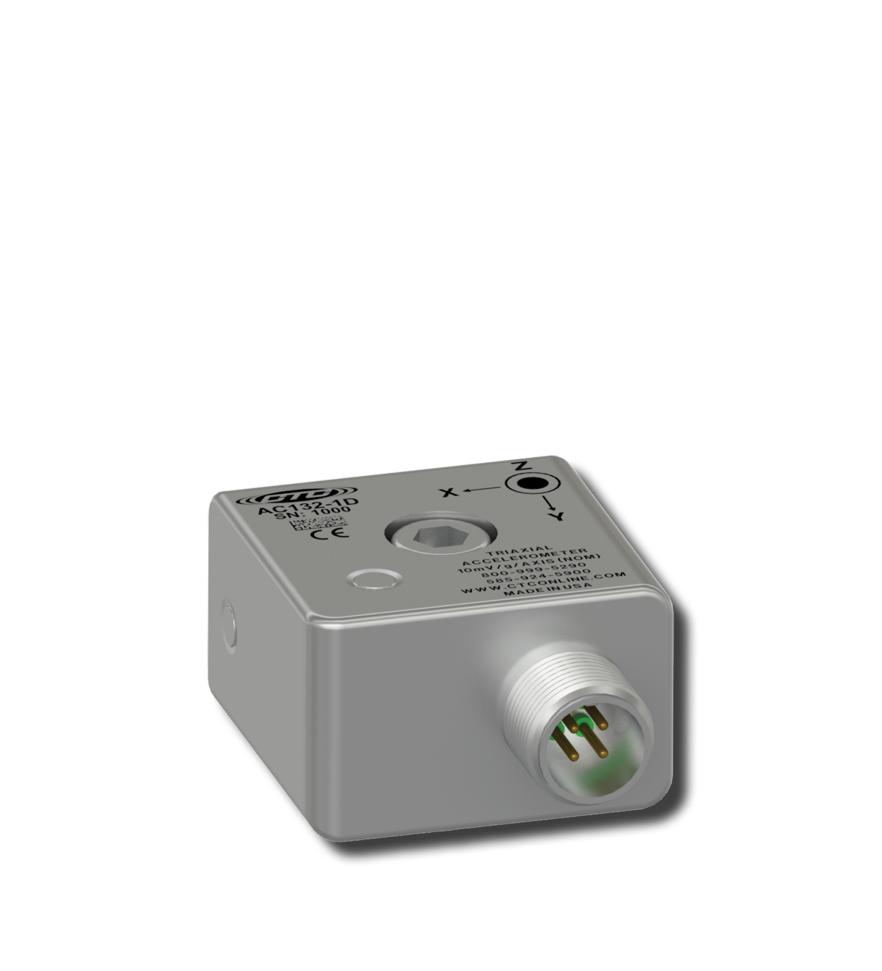
Triaxial Accelerometers
Measure vibration along all 3 axes (X, Y, and Z). Ideal for portable or permanent applications.
ULTRASOUND ACCELEROMETERS

Ultrasound Accelerometers
Are dynamic vibration IEPE sensors available in top and side exit configurations.
TEMPERATURE SENSORS
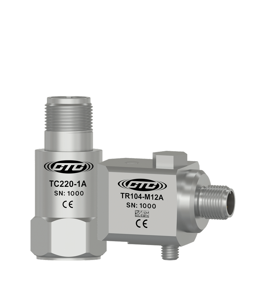
Temperature Sensors
Measure temperature or temperature and vibration. °C output option available. RTD and IEPE versions offered.
LOOP POWER SENSORS
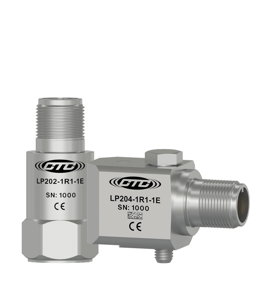
Loop Power Sensors
Our 4-20mA LP Sensors are available in three output styles: Velocity Output, Acceleration Output, and Dual Output - Loop Power and Dynamic Output. Hazardous Rated versions are also available.
TEST AND MEASUREMENT SENSORS
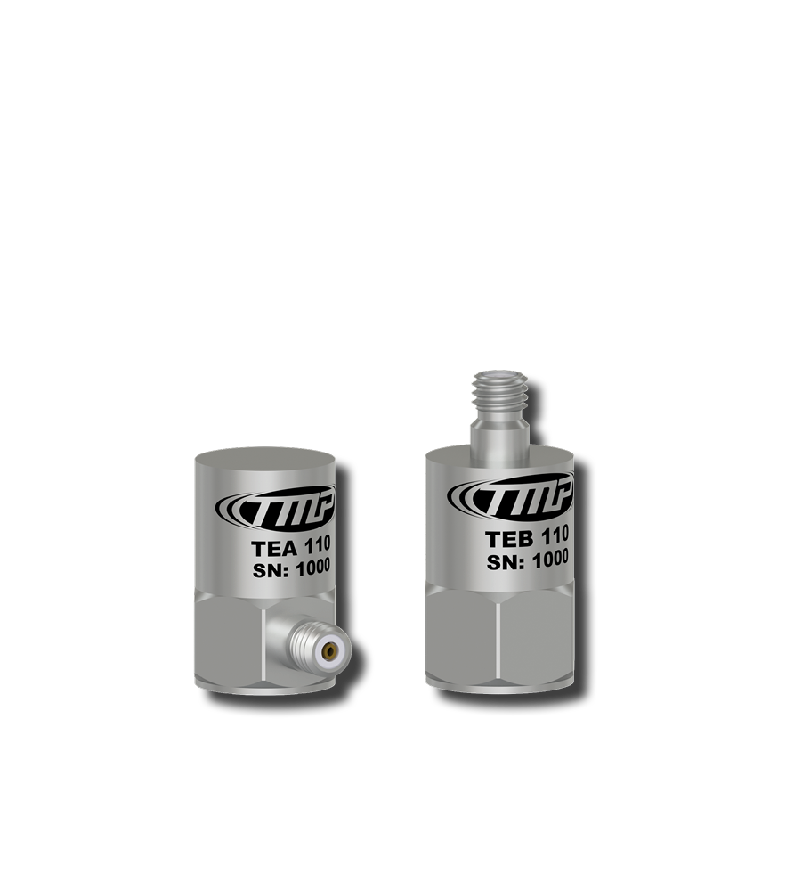
Test and Measurement Sensors
Are small, lightweight sensors for research applications. Top and side exit versions are available.
Choosing Your Accelerometer
All CTC sensors are manufactured with the same, robust IEPE design. However, understanding the basic selection criteria can help you determine which sensor is best for your application.
Sensitivity Tolerance
Every accelerometer will be calibrated to determine the sensitivity, and the actual measured output value must fall within the sensitivity tolerance.
Typical tolerances are ±5%, ±10%, ±15%, and ±20%, where 5% would be considered a premium tolerance and 20% would be considered a marginal tolerance. Typical user values are 10% and 15% for general purpose vibration measurements. If you were to choose a 100 mV/g accelerometer with a ±10% sensitivity tolerance, the calibrated output of the sensor could range from 90 mV/g (-10%) to 110 mV/g (+10%). However, if you were to choose a 500 mV/g accelerometer with a ±10% sensitivity tolerance, the calibrated output of the sensor could range from 450 mV/g (-10%) to 550 mV/g (+10%).
Frequency Response
Given the established sensitivity of the accelerometer, the allowable output at the calibration frequency will be identified as the sensitivity tolerance, but all other amplitudes will be bound by the frequency response limits. These limits are typically established at ±5%, ±10%, and ±3% dB above and below the measured sensitivity value, for those frequencies greater than or less than the calibration frequency. ±3% dB will be the largest frequency range and is normally considered to be the usable range or working range of the accelerometer.
Dynamic Range
The maximum and minimum amplitude that the accelerometer can measure is indicated by the dynamic range.
Typically the dynamic range is limited to ±5 VACPeak, but some 100 mV/g accelerometers are available with a dynamic range extended to ±8 VACPeak. If the normal bias voltage is 12 VDC, but can range from 10-14 VDC, the power supply must have greater potential than the bias voltage ± the voltage of the vibration signal.
The following examples illustrate this concept:
Given an 18 VDC power supply, 12 VDC bias voltage, and maximum vibration amplitude (Dynamic Range) of ±5 VAC, the combined voltage output would vary between 7 to 17 volts. This is within the limit of the power supply.
Given an 18 VDC power supply, 14 VDC bias voltage, and maximum vibration amplitude (Dynamic Range) of ±5 VAC, the combined voltage output would vary between 9 to 19 volts. This exceeds the upper limit of the power supply by 1 volt and will cause clipping of the vibration signal. In this case, a 20 VDC power supply would be required.
Mounting Hardware Explained
The industrial accelerometer is the primary vibration sensor needed for rotating equipment utilizing rolling element bearings. The vibrations generated by the machine will be transmitted through the casing of the machine to the base of the accelerometer where the Piezo ceramic reacts with the mass in a shearing mode to produce a charge output. The charge is converted to a voltage and amplified internally in the accelerometer for measurement by the vibration analyzer, data collector, or online monitoring system.
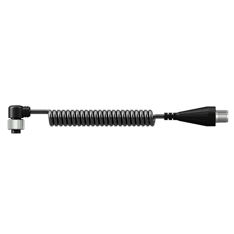
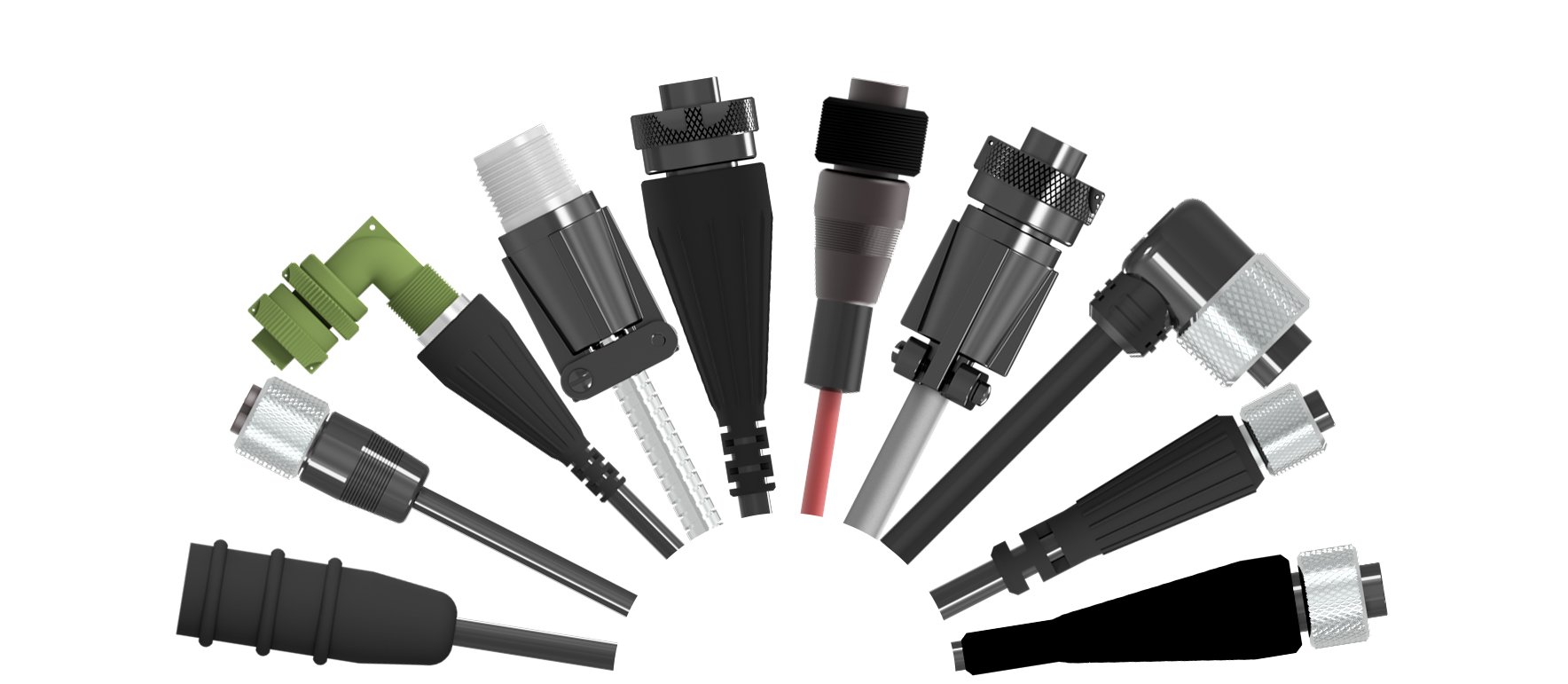
Cable Assemblies Explained
Cable assemblies carry the signal from the sensor to your data collection equipment.
Should a cable assembly get damaged or break, the vibration analyst will receive erroneous data. As a result, CTC offers the widest variety of cabling and connector options on the market. Our wide variety of options allows the user to create a customized cordset based on specific application needs and environmental data.
Use Our Cable Wizard to Build Your Custom Cable Assembly:
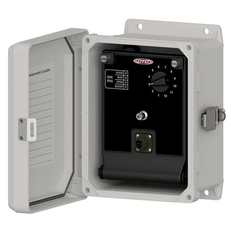
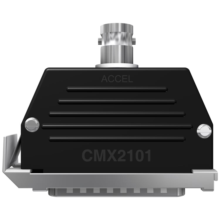
Enclosures Explained
At CTC, we offer the widest variety of junction boxes in the world.
Our solutions allow for the monitoring of remotely mounted vibration sensors, which would otherwise be restricted to human access due to safety considerations. Junction boxes allow for the cabling of up to 48 permanently mounted sensors to be routed to one single data collection point for ease of access, safety, and efficient data collection. Many CTC Junction Boxes also offer continuous output options for direct interface to online monitoring systems. Our enclosures are designed and built to last in the toughest industrial environments, to ensure your data is reliable and protected.
Data Collection Instrumentation Explained
The final piece to a vibration monitoring system is the way in which data is analyzed and presented through either a portable data collection device or online monitoring system.
All CTC products are compatible with all standard condition monitoring software. For portable data collection devices, we offer the widest variety of Data Collection Connectors, so that you can configure your cordset for direct interface into your device for fast, efficient, and reliable data collection.
Other Considerations - Sensor Mounting Techniques
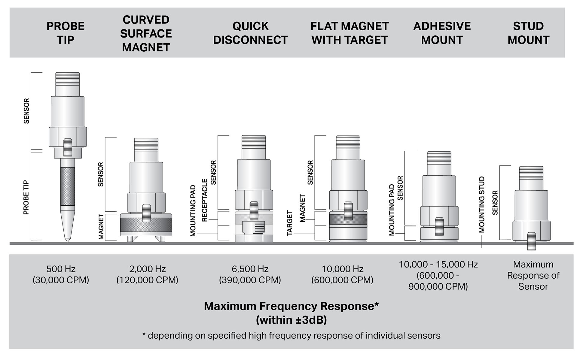
The accuracy of your high-frequency response is directly affected by the mounting technique that you select for the sensor. In general, the greater the mounting surface area contact between the sensor and the machine surface, the more accurate your high-frequency response will be.
High-frequency response is based on the sensor specified as well as the method of attachment (together as a system). Stud-mounted (or epoxy-mounted) sensors are often able to utilize the entire high-frequency measurement capability of a sensor because this technique will maximize the surface contact of the sensor on the machine. Conversely, a probe tip mounted sensor has very little surface area contact with the machine surface and offers very little high-frequency accuracy above 500 Hz (30,000 CPM).
Low-frequency response may be accurately obtained by all of the techniques illustrated above because low frequency is not based on the mounting system resonance of the sensor and attachment method. The ability to measure low-frequency vibrations will be a function of the sensor's specified capability to measure a given low frequency and independent of the mounting technique chosen.
The chart above offers a general guideline for the range of mounting techniques available and the corresponding frequency response expectations.
Other Considerations - Cabling
Temperature resistance, chemical compatibility, and environmental factors are key concerns in choosing the right cable assembly for your application. As a result, CTC offers a wide variety of jacket and connector materials in order to tailor your cordset to your specific environmental concerns.
Available cable jacket options:
- Fluorinated Ethylene Propylene (FEP)
- Polyurethane
- Lightweight Polyurethane
- PVC
- Thermoplastic Elastomer (TPE)
- Low Smoke Zero Halogen
Available cable armor options:
- Stainless Steel Braided Sheathing
- Stainless Steel Armor
- Hydraulic Hose Armor
At CTC, we often get the question of whether or not a user should use an integral cable sensor or a cable assembly. CTC recommends integral cable sensors only for submersible applications. For all other applications, CTC recommends choosing a standard connector exit sensor and pairing it with a cordset enables the user to take advantage of our component-based system. should there be damage to your cordset or the sensor only one of the components needs to be replaced.
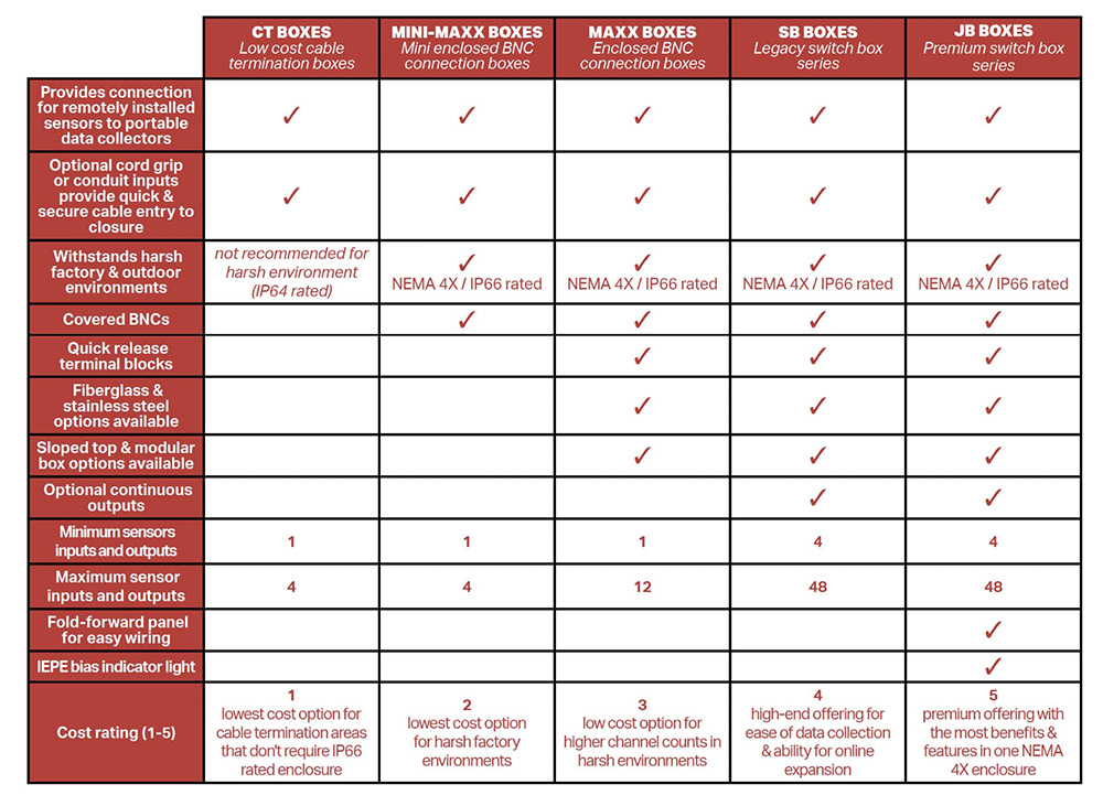
Junction Box Comparison
CTC offers a variety of low-cost, standard, and premium junction boxes in both single axis, dual input and output, and triaxial input and output options. Environmental considerations, desired channel count, and the ability for continuous output are key considerations in deciding what junction box is best for you.