Dynamic Output vs. 4-20 mA Accelerometers
Click here to download the printer-friendly pdf version of this blog post
Choosing the best style of accelerometer for a specific application is a common consideration facing vibration analysts.
In particular, determining whether to use a dynamic output accelerometer or a 4-20 mA output accelerometer is a frequent decision that must be made by analysts. While these styles of accelerometers share some similarities, they also have basic differences and cannot be used interchangeably.
Similarities and Differences
Both dynamic output accelerometers and 4-20 mA output accelerometers frequently have the identical form factor and electrical connection. The internal sensing elements are also nearly identical.
The main difference between these accelerometers is in the way the processor and internal amplifier process and output the vibration signal affecting the sensor.

AC102-1A Dynamic Output Accelerometer

LP202-1R1-1E 4-20 mA Output Accelerometer
Understanding Dynamic Output Accelerometers
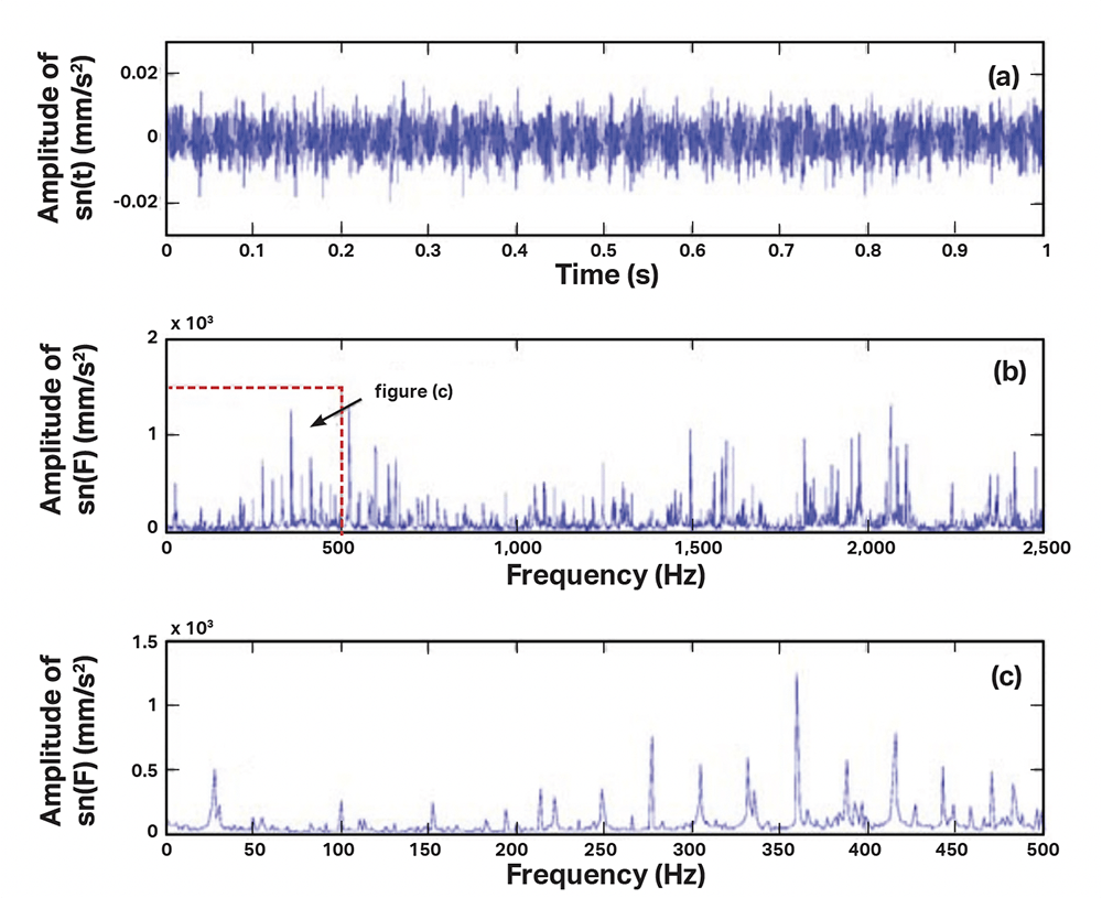
Dynamic vibration accelerometers output an AC voltage riding on a DC bias voltage. The raw output is usually called the time waveform and contains all the information required for a data analyzer or computer to perform a Fast Fourier Transformer (FFT), a mathematical operation that breaks the time waveform down into its frequency-based components, as illustrated in the following graphs, and is output as a spectrum.
While valuable as a diagnostic tool, time waveform and spectra are not used by most PLC, DCS, or SCADA-type systems. This means the dynamic output accelerometer is not well suited for use as a continuous monitoring tool without a specialized system or processor unit to modify the signal.

Pictured above:
A typical plot from a dynamic analyzer of the output from a dynamic accelerometer.
The top plot (a) is the raw output of the sensor called the time waveform.
The middle plot (b) is an FFT spectrum in which the data analyzer has performed a Fast Fourier Transformation to break the time waveform into its component frequencies.
This information is expanded in the lower plot (c) to focus on frequencies of interest in diagnosing vibration problems which can be used to determine what component of the machine might be deteriorating.
Understanding 4-20 mA Output / Loop Power Accelerometers
4-20 mA or loop power accelerometers output the same signal sent by the same sensing element, but in a different way.
Loop power accelerometers start by selecting only the portion of the time waveform within a frequency band which is selected at the time of manufacturing. This band will generally eliminate the very high and very low frequencies which are usually less likely to be problem areas.
After eliminating the unwanted frequencies, the remainder of the data from the time waveform is aggregated into an overall number proportional to the full scale of the accelerometer, which is also selected at the time of manufacture.
As a machine bearing or gear box becomes worn, the surfaces deteriorate and cause vibrations to increase. These increases cause an increase in the overall vibration output of the accelerometer, and a vibration analyst can be sent out to troubleshoot the problem before it causes a shutdown.
Unlike dynamic output accelerometers, loop power accelerometer signals cannot be broken down into their frequency components, as some of the information from the time waveform has been stripped away from the signal prior to its being passed along to the monitoring system.

Pictured above:
Typical type of information provided by a 4-20 mA output accelerometer, with slight fluctuations probably based on the process and larger changes at particular points.
Note the red line, which is the alarm point. Once overall vibration levels pass the red line, an alarm or shutdown would be triggered.
