SAG Mill Vibration Monitoring Guide
Use this link to view the printer-friendly pdf version of this blog post
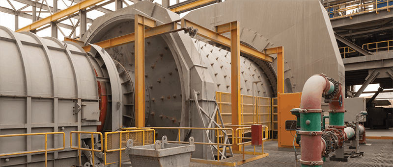
SAG mills are among the most critical rotating assets in mineral processing operations.
Heavy loading, low rotational speeds, high transmitted forces, and continuous operation create demanding conditions.
A properly designed vibration monitoring system can provide maintenance teams with valuable condition data to help identify developing mechanical problems and support planned maintenance before equipment reliability or production is impacted.
Potential conditions to monitor:
-
Rolling-element bearing defects
-
Gear mesh abnormalities
-
Lubrication-related conditions
-
Misalignment
-
Mechanical looseness
-
Unbalance
-
Motor bearing condition
A Different Approach to Low-Frequency SAG Mill Monitoring
SAG mills present a unique vibration monitoring challenge. Their slow rotational speeds require a sensor capable of detecting very low-frequency vibration, while the severe vibration generated during operation can demand a much larger measurement range.
A traditional approach is to use a 500 mV/g low-frequency accelerometer, such as the AC133.
The increased sensitivity makes 500 mV/g sensors well suited for detecting low-amplitude vibration on slow-speed machinery.
However, SAG mills can experience periods of very intense vibration. A typical 500 mV/g sensor has a dynamic range of approximately ±16 g, creating the potential for sensor saturation when vibration levels become sufficiently high.
CTC’s Solution: AC203 and AC204
Rather than increasing sensor sensitivity to achieve low-frequency response, CTC offers the AC203 and AC204, specially designed 100 mV/g accelerometers that maintain low-frequency measurement capabilities while providing significantly greater dynamic range.
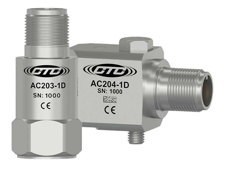
- Sensitivity: 100 mV/g with ±10% sensitivity tolerance
- Frequency Response: Down to 0.1 Hz (6 CPM)
- Dynamic Range: Approximately ±80 g
- Connector: Two-pin top exit or side exit connector
- Designed For: Applications requiring both low-frequency and high-frequency vibration detection. This combination is particularly valuable on SAG mills.
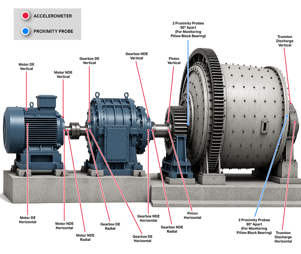
Common Sensor Placement
Complete Your System
Selecting the right accelerometer is only one part of building a reliable SAG mill monitoring system. Mining environments introduce heavy dust, debris, moisture, impact, and abrasion, making the protection of the entire measurement path especially important.
Protect the Signal with Armored Cabling
Cables installed around SAG mills can be exposed to abrasive debris, mechanical damage, and demanding routing conditions. For these environments, armor-protected cable is commonly selected to provide additional mechanical protection.
Popular armored cable options include:

- Conductors: Two
- Cabling Style: Twisted, shielded pair cable
- Cable Jacket: Lightweight red FEP jacket
- Outer Armor: Stainless steel
- Maximum Temperature: 392 °F (200 °C)

- Conductors: Two
- Cabling Style: Twisted, shielded pair cable
- Cable Jacket: Red FEP jacket
- Outer Armor: Hydraulic hose
Maximum Temperature: 212 °F (100 °C)

- Conductors: Two
- Cabling Style: Twisted, shielded pair cable
- Cable Jacket: Red FEP jacket
- Outer Armor: Braided stainless steel
- Maximum Temperature: 392 °F (200 °C)
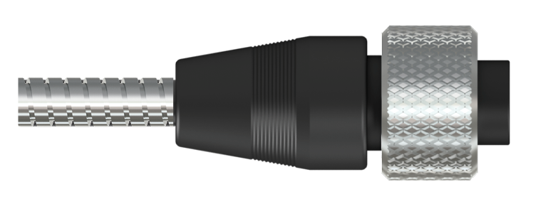
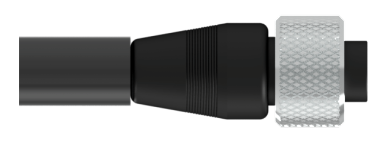
Cable selection can be matched to the requirements of the installation and paired with CTC molded connectors, including A2A, A2N, and A2L, to create a robust connection at the sensor.
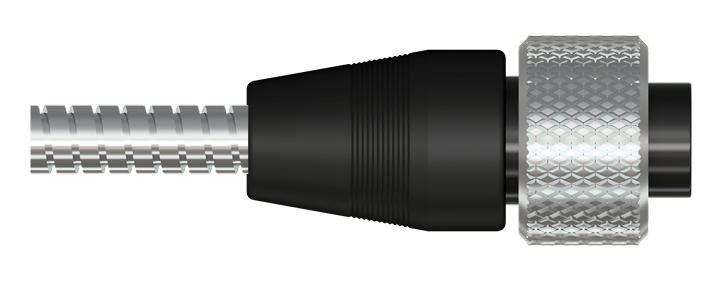
- Sockets: Two socket MIL-style
- Material: Polycarbonate molded
- Application Type: Permanent mount
- Maximum Temperature: 250 °F (121 °C)
- Conductors: Two socket MIL-style
- Material: Nylon molded
- Application Type: Permanent mount
- Maximum Temperature: 250 °F (121 °C)
- Conductors: Two socket MIL-style
- Material: Polycarbonate molded
- Application Type: Permanent mount; for use with hydraulic hose armored cable only
- Maximum Temperature: 212 °F (100 °C)
Centralize Connections with a Junction Box
Permanently installed sensors can be routed back to a CTC junction box, providing an organized and accessible location for vibration data collection while reducing the need to repeatedly access measurement points directly on the SAG mill.
CTC enclosure options include:
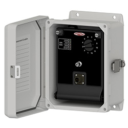
Fiberglass Junction Box
(JB110 standard size shown)
Durable, non-metallic enclosure option for industrial environments
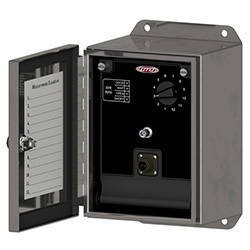
Stainless Steel Junction Box
(JB210 standard size shown)
Rugged enclosure construction for demanding installations
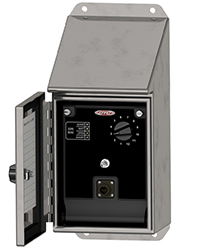
Slope Top Stainless Steel Junction Box
(JB310 shown)
Particularly well suited for mining applications where dust and debris accumulation is a concern. The sloped enclosure top helps discourage material from collecting on the junction box